


WirelessHART Fieldgate SWG70
Operation
E Hauser
31
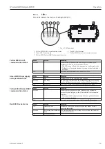
The function of the buttons is as follows:
Buttons
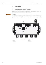
6.1.3
DIP switches
WARNING!
• When Fieldgate SWG70 is installed in Ex-Zone 2 and connected to the power supply, the
operation of DIP switches is permitted only in the absence of any potentially explosive
atmosphere.
NOTICE!
• The same functions can be initiated from the Fieldgate SWG70 Web interface and DTM.
See Chapter 8.3 "Interfaces (wired communication)" on page 50.
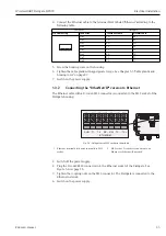
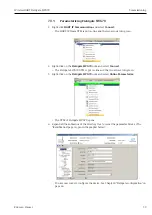
Fieldgate SWG70 has one 8-gang DIP switch. Fieldgate SWG70 is delivered with all DIP
switches set to ON and with all DIP switch functions set by software controls.
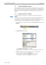
Fig. 6-4: DIP switches
Buttons
Function
Procedure
Button P1
Configuration reset
Press the button for more than 3 seconds.
– All Fieldgate SWG70 configuration parameters are reset to
factory settings with exception of the parameters set by button
P2 and button P1 + P2.
– After approx. 3 seconds, all LEDs light up to confirm the reset.
Button P2
Communication reset
Press the button for more than 3 seconds.
– All Fieldgate SWG70 configuration parameters related to the
wired communication channels are reset to factory settings.
– After approx. 3 seconds, all LEDs light up to confirm the reset.
Button P1 + P2
DIP switch 8 OFF
Password reset
Press buttons P1 and P2 simultaneously for more than 3 seconds.
– All Fieldgate SWG70 passwords are reset to the factory settings.
– Passwords are used for access to the Command Line Interface
and the Web Server (HTTPS).
– For Web Server User name: admin; Password: admin
– After approx. 3 seconds, all LEDs light up to confirm the reset.
Button P1 + P2
DIP switch 8 ON
Network manager reset
Press buttons P1 and P2 simultaneously for more than 3 seconds.
– The Fieldgate SWG70 join key, network ID, radio power and
access mode are reset to factory settings.
– After approx. 3 seconds, all LEDs light up to confirm the reset.
1 DIP switches 1 to 4: HART device address
2 DIP switches 5 and 6:
Baud rate of RS-485 interface
3 DIP switch 7: RS-485 terminating resistor
4 DIP switch 8: Security mode
+24V
+24V
0V
0V
LINE1
LINE2
A
B
SHD
RS485
T1
T2
RX– RX+ TX– TX+
ON
OFF
SHD
A
B
SHD
RS485
ETHERNET
1
2
3
4
ON
OFF
1 2 3 4 5 6 7 8


