background image

ISEmax CAS40D

Hauser

3

Table of contents

Safety instructions  . . . . . . . . . . . . . . . .  4

1.1 

Designated use   . . . . . . . . . . . . . . . . . . . . . . . . . . . .  4

1.2 

Installation, commissioning and operation  . . . . . . . .  4

1.3 

Operational safety  . . . . . . . . . . . . . . . . . . . . . . . . . .  4

1.4 

Return . . . . . . . . . . . . . . . . . . . . . . . . . . . . . . . . . . .  4

Identification  . . . . . . . . . . . . . . . . . . . .  5

2.1 

Nameplate   . . . . . . . . . . . . . . . . . . . . . . . . . . . . . . .  5

2.2 

Interpreting the order code   . . . . . . . . . . . . . . . . . . .  5

2.3 

Scope of delivery  . . . . . . . . . . . . . . . . . . . . . . . . . . .  5

2.4 

Certificates and approvals   . . . . . . . . . . . . . . . . . . . .  5

Installation . . . . . . . . . . . . . . . . . . . . . .  6

3.1 Incoming 

acceptance, 

transport, storage . . . . . . . . . .  6

3.2 

Installation conditions  . . . . . . . . . . . . . . . . . . . . . . .  6

3.3 

Installation instructions  . . . . . . . . . . . . . . . . . . . . . .  7

3.4 

Installation example   . . . . . . . . . . . . . . . . . . . . . . . .  9

3.5 

Post-installation check  . . . . . . . . . . . . . . . . . . . . . .  10

Wiring  . . . . . . . . . . . . . . . . . . . . . . . .  11

4.1 

Connecting to the transmitter   . . . . . . . . . . . . . . . .  11

4.2 

Electrode connection in the sensor:  . . . . . . . . . . . .  11

4.3 

Post-connection check . . . . . . . . . . . . . . . . . . . . . .  12

Calibration . . . . . . . . . . . . . . . . . . . . .  13

5.1 

Calibration modes  . . . . . . . . . . . . . . . . . . . . . . . . .  13

5.2 

Calibration and adjustment of ion-selective electrodes    
13

5.3 

Calibration   . . . . . . . . . . . . . . . . . . . . . . . . . . . . . .  14

5.4 

Checking the calibration  . . . . . . . . . . . . . . . . . . . .  14

Maintenance. . . . . . . . . . . . . . . . . . . .  15

6.1 

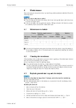
Maintenance schedule . . . . . . . . . . . . . . . . . . . . . .  15

6.2 

Cleaning the membrane   . . . . . . . . . . . . . . . . . . . .  15

6.3 

Replacing membrane cap and electrolyte  . . . . . . . .  15

Accessories. . . . . . . . . . . . . . . . . . . . .  18

7.1 

Assembly holder  . . . . . . . . . . . . . . . . . . . . . . . . . .  18

7.2 

Maintenance kits . . . . . . . . . . . . . . . . . . . . . . . . . .  18

7.3 

Electrodes  . . . . . . . . . . . . . . . . . . . . . . . . . . . . . . .  18

7.4 

Standard solutions  . . . . . . . . . . . . . . . . . . . . . . . . .  19

7.5 

Compressed air cleaning   . . . . . . . . . . . . . . . . . . . .  20

Troubleshooting . . . . . . . . . . . . . . . . .  21

8.1 

Troubleshooting instructions  . . . . . . . . . . . . . . . . .  21

8.2 

Spare parts   . . . . . . . . . . . . . . . . . . . . . . . . . . . . . .  22

8.3 

Return . . . . . . . . . . . . . . . . . . . . . . . . . . . . . . . . . .  23

8.4 

Disposal   . . . . . . . . . . . . . . . . . . . . . . . . . . . . . . . .  23

Technical data . . . . . . . . . . . . . . . . . . . 24

9.1 

Input  . . . . . . . . . . . . . . . . . . . . . . . . . . . . . . . . . . . 24

9.2 

Performance characteristics  . . . . . . . . . . . . . . . . . . 24

9.3 

Environment  . . . . . . . . . . . . . . . . . . . . . . . . . . . . .  25

9.4 

Process   . . . . . . . . . . . . . . . . . . . . . . . . . . . . . . . . . 26

9.5 

Mechanical construction   . . . . . . . . . . . . . . . . . . . . 26

Index . . . . . . . . . . . . . . . . . . . . . . . . . . . . . . 27

Summary of Contents for ISEmax CAS40D

Page 1: ...BA491C 07 EN 01 11 71130408 Operating Instructions ISEmax CAS40D Ion selective sensor...

Page 2: ...Consequences of non compliance if applicable Protection measures This note alerts you to a dangerous situation If you do not avoid the dangerous situation it may result in death or serious injury CAU...

Page 3: ...4 2 Electrode connection in the sensor 11 4 3 Post connection check 12 5 Calibration 13 5 1 Calibration modes 13 5 2 Calibration and adjustment of ion selective electrodes 13 5 3 Calibration 14 5 4 C...

Page 4: ...nd must follow the instructions they contain Before commissioning the entire measuring point make sure all the connections are correct Ensure that electrical cables and hose connections are not damage...

Page 5: ...the nameplate into the search field at the following address www products endress com order ident 2 3 Scope of delivery The scope of delivery comprises 1 sensor in version as ordered 1 socket wrench 1...

Page 6: ...mplete and matches your order and the shipping documents Pack the product for storage and transportation in such a way that it is reliably protected against impact and moisture The original packaging...

Page 7: ...d remove the protection guard 2 2 Unscrew the coupling nut 3 3 Pull the electrode holder out of the sensor and release the electrode cable on a dummy electrode placeholder must be present for impermea...

Page 8: ...just the chain length and the cross bearer for the holder in such a way that the sensor is immersed in the medium up to the coupling nut and is approximately 0 5 m 1 64 ft from the basin rim 4 Route t...

Page 9: ...er e g CYH112 Weather protection cover absolutely essential if mounting the transmitter outdoors Compressed air generator if no compressed air available on site a0015206 Fig 6 Example measuring system...

Page 10: ...Post installation check After mounting check all the connections to ensure they are secure and leak tight Check all cables and hoses for damage Check whether the cables are routed such that they are f...

Page 11: ...ug or using the fixed cable at the terminal blocks version fixed cable ferrules a0012460 Fig 7 Sensor connection The maximum cable length is 100 m 328 ft 4 2 Electrode connection in the sensor All ele...

Page 12: ...or cable externally damaged Visual check Electrical connection Notes Does the supply voltage of the transmitter match the data on the nameplate Are the installed cables strain relieved and not twisted...

Page 13: ...ensors are used for measured value compensation of ion selective electrodes Measured value of temperature sensor for temperature compensation pH measured value for pH compensation of ammonium optional...

Page 14: ...also be interpreted as part of the measuring signal and thus cause measuring errors When measuring in wastewater the potassium ion which is chemically similar to the ammonium ion can cause higher meas...

Page 15: ...for cleaning purposes The optional chloride electrode has a crystal instead of a membrane To clean it place some sandpaper 600 grit on an even surface Now rub the sensor with the crystal area facing...

Page 16: ...ght with the cable connection head facing downwards and screw on the membrane cap until it is hand tight 14 6 Turn the electrode around and remove any air bubbles by holding the electrode vertically a...

Page 17: ...ket wrench SW17 11 but in the opposite direction 2 Connect the electrode connector to the cable 10 opposite direction 3 Carefully push the electrode holder and the air hose back into the sensor 4 Scre...

Page 18: ...l version Order as per product structure Technical Information TI430C 07 en 7 2 Maintenance kits Membrane kit 2 Membrane caps with chloride only one membrane cap with crystal Electrolyte Order numbers...

Page 19: ...Ammonium nitrate 1 molar 2 Potassium chloride 1 molar Container size A 250 ml 8 45 fl oz Transport documents 1 Standard documents 2 Incl dangerous goods sheets 3 Safety data sheet Certificate A None...

Page 20: ...ix times the cleaning time Avoid condensation in the pressurized hoses Cleaning unit in the housing 230 V or 115V IP 65 Conveying rate at atmospheric pressure 50 l min 13 2 gal min Power consumption 2...

Page 21: ...ting in the Operating Instructions for the transmitter If need be carry out a test on the transmitter Problem Check Solution No display no sensor reaction Line voltage at transmitter Sensor connected...

Page 22: ...able for electrodes 71130358 3 7 Kit CAS40D seal set Flat seal for electrode holder 3 Seal for electrode holder Seals for electrodes 5x Seal for cleaning nozzle Coupling nut 7 71130360 4 Temperature s...

Page 23: ...ains electronic components and the product must therefore be disposed of as electronic waste Please observe local regulations 9 Ion selective electrodes electrode complete length 120 mm Ammonium Nitra...

Page 24: ...nium 0 1 to 1000 mg l NH4 N Nitrate 0 1 to 1000 mg l NO3 N Potassium 1 to 1000 mg l Chloride 1 to 1000 mg l 9 2 Performance characteristics Response time t90 Ammonium 2 min Nitrate 2 min Potassium 2 m...

Page 25: ...ction IP 68 Electromagnetic compatibility Interference emission and interference immunity as per EN 61326 Namur NE21 Sensor Temperature pH Potassium1 2 1 The fluctuations in concentration not the abso...

Page 26: ...ght Approx 3 5 kg 7 7 lbs Material Process connection Pg 13 5 Compressed air connection for hose with AD 8 mm Sensor Protection guard Electrode holder Flat seals O rings for electrode holder and senso...

Page 27: ...n instructions Electrodes 7 Ion selective electrodes Interference ion compensation 14 M Maintenance 15 Maintenance schedule 15 Material 26 Maximum measured error 24 Maximum operating life 25 Measured...

Page 28: ...ISEmax CAS40D 28 Endress Hauser T Technical data 24 Transmitter connection 11 Transport 6 Troubleshooting 21 Troubleshooting instructions 21 U Use 4 W Weight 26 Wiring 11...

Page 29: ...ISEmax CAS40D Endress Hauser 29...

Page 30: ...ISEmax CAS40D 30 Endress Hauser...

Page 31: ...____________________________________________________________________________________________ ___________________________________________________________________________________________________________...

Page 32: ...BA491C 07 EN 01 11 FM9...

Reviews: