background image

Micropilot FMR56, FMR57 FOUNDATION Fieldbus

Mounting

Hauser

21

5.9  

Turning the display

5.9.1  

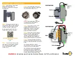
Opening the cover

2.

1.

3 mm

  A0021430

1. Loosen the screw of the securing clamp of the electronics compartment cover using an

Allen key (3 mm) and turn the clamp 90 ° counterclockwise.

2. Unscrew the electronics compartment cover and check the cover seal; replace it if

necessary.

5.9.2  

Turning the display module

1.

2.

  A0036401

1. Pull out the display module with a gentle rotational movement.
2. Turn the display module to the desired position: Max. 8 × 45 ° in each direction.
3. Feed the coiled cable into the gap between the housing and main electronics module

and plug the display module into the electronics compartment until it engages.

Summary of Contents for FOUNDATION Fieldbus Micropilot FMR56

Page 1: ...tions they are not a substitute for the Operating Instructions pertaining to the device Detailed information about the device can be found in the Operating Instructions and the other documentation Available for all device versions via Internet www endress com deviceviewer Smart phone tablet Endress Hauser Operations App KA01127F 00 EN 03 22 00 71575727 2022 08 01 ...

Page 2: ...t ord cd Ser no www endress com deviceviewer Endress Hauser Operations App XXXXXXXXXXXX XXXXX XXXXXX XXX XXXX XX Serial number 1 3 2 A0023555 2 About this document 2 1 Symbols used 2 1 1 Safety symbols DANGER This symbol alerts you to a dangerous situation Failure to avoid this situation will result in serious or fatal injury ...

Page 3: ...minals that must be connected to ground prior to establishing any other connections The ground terminals are located on the inside and outside of the device Interior ground terminal protective earth is connected to the mains supply Exterior ground terminal device is connected to the plant grounding system 2 1 3 Tool symbols Tool symbols Flat blade screwdriver Allen key Open ended wrench 2 1 4 Symb...

Page 4: ...es 3 2 Intended use Application and media The measuring device described in these Operating Instructions is intended for continuous non contact level measurement primarily in bulk solids Because of its operating frequency of approx 26 GHz a maximum radiated pulsed power of 23 3 mW and an average power output of 0 076 mW the device can also be used without restrictions outside closed metal vessels ...

Page 5: ...ation the sensor may reach a temperature close to the medium temperature Danger of burns from contact with surfaces In the event of elevated fluid temperatures ensure protection against contact to prevent burns 3 3 Workplace safety When working on and with the device Wear the required personal protective equipment as per national regulations 3 4 Operational safety Risk of injury Operate the device...

Page 6: ...ystem meets the legal requirements of the applicable EAC guidelines These are listed in the corresponding EAC Declaration of Conformity along with the standards applied The manufacturer confirms successful testing of the device by affixing to it the EAC mark 4 Incoming acceptance and product identification 4 1 Incoming acceptance Check the following during incoming acceptance Are the order codes o...

Page 7: ...ransport the measuring device to the measuring point in its original packaging or by the process connection Always secure lifting equipment slings eyes etc to the process connection and never to the electronic housing or antenna horn Pay attention to the center of gravity of the device so that it does not tilt or slip unintentionally Follow the safety instructions and transport conditions for devi...

Page 8: ...is not smooth corrugated iron welding seams joints etc it is advisable to maintain the greatest possible distance from the wall Where necessary use an alignment unit to avoid interference reflections from the vessel wall 1 Use of a weather protection cover protection from direct sunlight or rain 2 Installation in the center interference can cause signal loss 3 Do not install above the filling curt...

Page 9: ... Fieldbus Mounting Endress Hauser 9 5 2 Orientation 5 3 Internal vessel fittings α β A0018946 Avoid the location of internal fittings limit switches temperature sensors struts etc inside the signal beam Take into account the beam angle ...

Page 10: ...ed at an angle to scatter the radar signals help prevent interference echoes 5 5 Beam angle The beam angle is defined as the angle α at which the energy density of the radar waves reaches half the value of the maximum energy density 3dB width Microwaves are also emitted outside the signal beam and can be reflected off interfering installations ...

Page 11: ...ngle α and the distance D FMR56 Antenna size 80 mm 3 in 100 mm 4 in Beam angle α 10 8 Distance D Beam diameter W 3 m 9 8 ft 0 53 m 1 7 ft 0 42 m 1 4 ft 6 m 20 ft 1 05 m 3 4 ft 0 84 m 2 8 ft 9 m 30 ft 1 58 m 5 2 ft 1 26 m 4 1 ft 12 m 39 ft 2 1 m 6 9 ft 1 68 m 5 5 ft 15 m 49 ft 2 63 m 8 6 ft 2 10 m 6 9 ft 20 m 66 ft 3 50 m 11 ft 2 80 m 9 2 ft 25 m 82 ft 4 37 m 14 ft 3 50 m 11 ft 30 m 98 ft 5 25 m 17...

Page 12: ... Antenna size 200 mm 8 in 250 mm 10 in Beam angle α 4 3 5 Distance D Beam diameter W 5 m 16 ft 0 35 m 1 1 ft 0 30 m 1 ft 10 m 33 ft 0 70 m 2 3 ft 0 61 m 2 ft 15 m 49 ft 1 05 m 3 4 ft 0 92 m 3 ft 20 m 66 ft 1 40 m 4 6 ft 1 22 m 4 ft 30 m 98 ft 2 10 m 6 9 ft 1 83 m 6 ft 40 m 131 ft 2 79 m 9 2 ft 2 44 m 8 ft 50 m 164 ft 3 50 m 11 ft 3 06 m 10 ft 60 m 197 ft 4 19 m 14 ft 3 70 m 12 ft 70 m 230 ft 4 90 ...

Page 13: ...e gland to aid the alignment This marking must be aligned towards the tank wall as much as possible 90 90 90 90 90 A0019434 Depending on the device version the marking may be a circle or two parallel lines Information concerning nozzles H øD A0016868 2 Nozzle diameter and height for horn antennas with slip on flange ØD Maximum nozzle height Hmax 80 mm 3 in 300 mm 11 8 in 100 mm 4 in 400 mm 15 8 in...

Page 14: ...the mounting bracket and transmitter housing Risk of electrostatic charge Integrate the mounting bracket in the local potential equalization system 5 6 3 Horn antenna FMR57 Alignment Ideally the horn antenna should be installed vertically To avoid interference reflections or for optimum alignment in the vessel the Micropilot can be swiveled by 15 in all directions with the optional alignment devic...

Page 15: ...uld project out of the nozzle If this is not possible for mechanical reasons larger nozzle heights can be accepted Hmax A0016825 4 Nozzle height for horn antenna FMR57 Antenna Maximum nozzle height Hmax valid for antennas without an antenna extension Horn 80mm 3 260 mm 10 2 in Horn 100mm 4 480 mm 18 9 in Please contact the manufacturer s support service for applications with nozzles that are highe...

Page 16: ...5 in all directions using the optional alignment unit Information concerning nozzles Case 1 Ideally the parabolic antenna should project fully out of the nozzle 1 Particularly when using the alignment device it is important to ensure that the parabolic reflector is projecting out of the nozzle ceiling so as not to inhibit alignment Case 2 For applications with higher nozzles it may be necessary to...

Page 17: ...on with small flange If the flange is smaller than the parabolic reflector the device can be mounted in one of the following ways Standard installation the parabolic reflector must be dismantled in this case Installation with hinged flange Standard installation H øD 1 A0018874 1 Nozzle Antenna size ØD H without antenna extension 200 mm 8 in 173 mm 6 81 in 50 mm 1 96 in 250 mm 10 in 236 mm 9 29 in ...

Page 18: ...8 5 6 5 Alignment unit for FMR57 An angle of inclination of up to 15 in all directions can be set for the antenna axis using the alignment unit The alignment unit is used to optimally align the radar beam with the bulk solid 15 15 A0016931 6 Micropilot FMR57 with alignment unit ...

Page 19: ... applications with strong dust emissions the integrated purge air connection can prevent the antenna from becoming clogged Pulse operation is recommended 1 A0016932 7 Micropilot FMR57 with purge air connection 1 Purge air connection NPT or G Purge air pressure range Pulse operation max 6 bar 87 psi Continuous operation 200 to 500 mbar 3 to 7 25 psi Always use dry purge air In general only purge to...

Page 20: ...hermal radiation or convection The insulation should not be higher than the neck of the device 1 5 8 Turning the transmitter housing To provide easier access to the connection compartment or display module the transmitter housing can be turned max 350 8 mm 8 mm 2 3 1 A0032242 1 Unscrew the securing screw using an open ended wrench 2 Rotate the housing in the desired direction 3 Tighten the securin...

Page 21: ... counterclockwise 2 Unscrew the electronics compartment cover and check the cover seal replace it if necessary 5 9 2 Turning the display module 1 2 A0036401 1 Pull out the display module with a gentle rotational movement 2 Turn the display module to the desired position Max 8 45 in each direction 3 Feed the coiled cable into the gap between the housing and main electronics module and plug the disp...

Page 22: ...ment 1 2 2 5 Nm 3 mm A0021451 1 Screw down the cover of the electronics compartment 2 Turn the securing clamp 90 in the clockwise direction and using an Allen key 3 mm tighten the screw of the securing clamp on the electronics compartment cover with 2 5 Nm 6 Electrical connection 6 1 Connecting requirements 6 1 1 Terminal assignment ...

Page 23: ... 3 and 4 without integrated overvoltage protection 3 Connection switch output open collector terminals 3 and 4 with integrated overvoltage protection 4 Connection PROFIBUS PA FOUNDATION Fieldbus terminals 1 and 2 with integrated overvoltage protection 5 Terminal for cable shield Block diagram PROFIBUS PA FOUNDATION Fieldbus Y I 2 3 1 2 3 4 1 4 A0036530 9 Block diagram PROFIBUS PA FOUNDATION Fieldb...

Page 24: ...ly output 1 Approval 2 Terminal voltage E 2 wire FOUNDATION Fieldbus switch output G 2 wire PROFIBUS PA switch output Non Ex Ex nA Ex nA ia Ex ic Ex ic ia Ex d ia XP Ex ta DIP CSA GP 9 to 32 V 3 Ex ia IS Ex ia Ex d ia IS XP 9 to 30 V 3 1 Feature 020 in the product structure 2 Feature 010 in the product structure 3 Input voltages up to 35 V do not damage the device Polarity dependent No FISCO FNICO...

Page 25: ...ice Connect the potential matching line to the outer ground terminal before applying the power supply Required tools accessories For devices with a cover lock Allen key AF3 Wire stripper When using stranded cables One ferrule for every wire to be connected 6 2 1 Opening cover 2 1 3 mm A0021490 1 Loosen the screw of the securing clamp of the connection compartment cover using an Allen key 3 mm and ...

Page 26: ...If using shielded cables Connect the cable shield to the ground terminal 6 2 3 Plug in spring force terminals The electrical connection of device versions without an integrated overvoltage protection is via plug in spring force terminals Rigid conductors or flexible conductors with ferrules can be inserted directly into the terminal without using the lever and create a contact automatically 3 0 12...

Page 27: ...FF configuration program The Cff file Common File Format cff The device description DD is in one of the following formats Device description format 4 sym ffo Device description format 5 sy5 ff5 Data for device specific DD Manufacturer ID 0x452B48 Device type 0x1028 Device revision 0x01 DD Revision Information and files available at www endress com www fieldcommgroup org CFF Revision 7 2 Integratio...

Page 28: ...the device for the measuring task and for the FF system 7 3 Device identification and addressing FOUNDATION Fieldbus identifies the device using its identification code device ID and automatically assigns it a suitable field address The identity code cannot be changed The device appears in the network display once you have started the FF configuration program and integrated the device into the net...

Page 29: ...ATA_TRANSFER_ TRDHROM xxxxxxxxxxx ANALOG_INPUT_1_ AI xxxxxxxxxxx ANALOG_INPUT_2_ UNK xxxxxxxxxxx DISCRETE_INPUT_ DI xxxxxxxxxxx MULTIPLE_AO_ MAO xxxxxxxxxxx ARITHMETIC_ AR xxxxxxxxxxx INPUT_SELECTOR_ ISEL xxxxxxxxxxx ANALOG_ALARM_ AAL xxxxxxxxxxx PID_ PID xxxxxxxxxxx MULTIPLE_DO_ MDO xxxxxxxxxxx SIGNAL_CHAR_ SC xxxxxxxxxxx INTEGRATOR_ IT xxxxxxxxxxx SERVICE_SENSOR_ TRDSRVSB xxxxxxxxxxx ADV_SETUP_ ...

Page 30: ...le discrete output block MDO 1 PID block PID 1 arithmetic block AR 1 signal characterizer block SC 1 input selector block ISEL 1 integrator block IT 1 analog alarm block AAL In addition to the pre instantiated blocks already mentioned the following blocks can also be instantiated 3 AI blocks AI 2 Discrete Input Blocks DI 1 PID block PID 1 arithmetic block AR 1 signal characterizer block SC 1 input...

Page 31: ...T_CONFIG SETUP SERVICE_SENSOR PV SV ESC OPEN OPEN E Device_01 F mm 4841 000 A0017217 14 Block configuration when device is delivered S Sensor PV Primary value level linearized SV Secondary value distance 7 5 Assignment of measured values CHANNEL in the AI block The input value of an analog input block is determined via the Channel parameter Channel Measured value 0 Uninitialized 211 Terminal volta...

Page 32: ...esource block and allows the parameters of the electronic nameplate Electronic Name Plate to be changed Setup This method is located in the SETUP transducer block and is used for basic configuration of the measurement parameters measurement units tank or vessel type medium empty and full calibration Linearization This method is located in the ADV_SETUP transducer block and allows the linearization...

Page 33: ...tag and error symbol if an error is active 1 2 Measured value symbols 1 3 Measured value 1 4 Unit 2 Measured value display bar graph 1 value 2 1 Bar graph for measured value 1 2 2 Measured value 1 including unit 2 3 Measured value symbols for measured value 1 2 4 Measured value 2 2 5 Unit for measured value 2 2 6 Measured value symbols for measured value 2 3 Visualization of a parameter here param...

Page 34: ...84 17 Display module 1 Operating keys Key assignment Key Navigate down in the picklist Edit the numerical values or characters within a function Key Navigate up in the picklist Edit the numerical values or characters within a function Key In the measured value display Pressing the key briefly opens the operating menu Pressing the key for 2 s opens the context menu In the menu submenu Pressing the ...

Page 35: ...ighter setting key and key press and hold keys simultaneously Increases the contrast darker setting 9 2 Opening the context menu Using the context menu the user can call up the following menus quickly and directly from the operational display Setup Conf backup disp Envelope curve Keylock on Calling up and closing the context menu The user is in the operational display 1 Press for 2 s The context m...

Page 36: ...special measuring conditions For converting the measured value scaling linearization For scaling the output signal Diagnostics Contains the most important parameters for diagnosing the condition of the device Expert menu n the Enter access code parameter enter 0000 if no customer specific access code has been defined Contains all parameters of the device including those that are already in one of ...

Page 37: ... 50 Operation Setup Main menu 0104 1 Display language English Español Français Display language English Deutsch à 0104 1 à Español Français Display language English Deutsch 0104 1 Betrieb Setup Hauptmenü Sprache Deutsch 0104 1 XX XX 1 2 3 4 A0029420 18 Taking the example of the local display ...

Page 38: ...surement D Distance L Level E Empty calibration zero point F Full calibration span 1 Setup Device tag Enter a unique name for the measuring point to identify the device quickly within the plant 2 Setup Distance unit Used for the basic calibration Empty Full 3 Setup Bin type Optimizes the signal filters for the respective bin type Note Workbench test deactivates all filters This option should exclu...

Page 39: ...setup Level Tank silo heightIf the parametrized measuring range Empty calibration differs significantly from the tank or silo height it is recommended to enter the tank or silo height in this parameter Example Continuous level monitoring in the upper third of a tank or silo Note For tanks with conical outlet this parameter should not be changed as in this type of applications Empty calibration is ...

Page 40: ...Commissioning Micropilot FMR56 FMR57 FOUNDATION Fieldbus 40 Endress Hauser Also for the Expert submenu GP01017F Description of device parameters FMR5x FOUNDATION Fieldbus ...

Page 41: ......

Page 42: ......

Page 43: ......

Page 44: ...www addresses endress com 71575727 71575727 ...

Reviews: