Nothing beats know-how
Endress Hauser
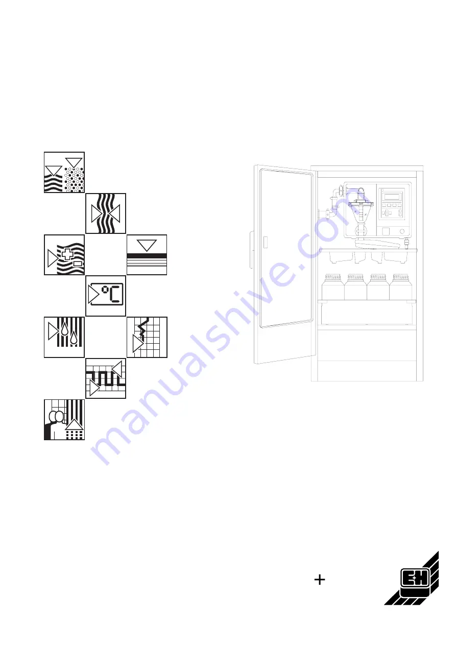
Multi-functionwater sampler
asp-station d 2
Installation and operating instructions
BA 034R/09/en/04.97Part No. 50051362
Page 1: ...Nothing beats know how Endress Hauser Multi function water sampler asp station d 2 Installation and operating instructions BA 034R 09 en 04 97 Part No 50051362...
Page 2: ......
Page 3: ...the following characters Hint Hints for better installation Attention Ignoring this note can lead to damage of the device or faulty operation Danger Ignoring this warning can lead to personal injury...
Page 4: ...ons shown are for the standard housing For wide housing dimensions see technical data Sampler asp station a left 1 Controller liqui box d 2 2 Distribution tray tap and tray 3 Bottle tray with bottles...
Page 5: ...ampling point recommendations 8 Foundation recommendations 9 Electrical installation 9 Power supply 9 Terminal box 10 Terminal connections 10 Outputs 10 Inputs 10 Control input 11 Connection examples...
Page 6: ...on and information 24 Base settings 26 Programmes Creating and changeover 28 Start stop operation 30 Service level 32 Operator settings 34 Changing analogue input 36 Sample distribution conversion 37...
Page 7: ...onnections can make the unit potentially dangerous Intentional disconnection or an open circuit of this earth connection is not permissible There are no components in the unit that can be repaired by...
Page 8: ...sampler close to large magnetic fields eg motors transformers large contactors etc Do not install the sampler in areas where it can be subject to high mechanical vibration Avoid shocks when transport...
Page 9: ...s where large solids particles are not required in the sample A Filter B Connector C Jubilee clip Filter order No 50038327 Recommendation Never submerge the hose against the flow direction If possible...
Page 10: ...nsions There are four 10 mm dia holes in the base of the cabinet B Defrost water drain C Possible cable entries Foundation recommendation on option For special version wide housing eg 24 x 2 5 l bottl...
Page 11: ...power supply the system must be without power Push both snap locks 1 inwards and hinge the blanking plate 2 downwards The terminal box 3 can now be seen Undo screws 4 and remove the terminal box lid T...
Page 12: ...e no alarm Contact open Power off Contact open Inverse Power on active alarm condition Contact open Power on not active no alarm Contact closed Power off Contact open KL5 2 is permanently connected wi...
Page 13: ...210 220 230 up to 260 Interface TTY Primo Bit To record sampling sequences and preset parameters Connect KL8 terminal 8 TXD to pin 24 on the Primo Bit Connect KL8 terminal 12 UTTY to pin 17 on the Pr...
Page 14: ...terrogated however the internal clock continues to run during power failure On return of power the unit initiates a self check any bottle changes required are not caught up The sampler now continues t...
Page 15: ...ng chamber until the conductivity level switch is activated sensors in the dosing chamber flange 4 The hose clamp is released and the sample flows into the composite container or bottles if operating...
Page 16: ...factory setting 200ml Addr 111 Set up bottle container volume factory setting 0 6l Always reset the dosing and bottle container volume values on initial installation and when either of these criteria...
Page 17: ...Uhr If bottle synchronisation is set to OFF in address 128 the automatic sequence starts with bottle 1 Bottle change takes place at the preset time addr 127 This is only valid if the actual programme...
Page 18: ...e next steps 1 Open cabinet door 2 Switch unit off Operate the OFF 4 push button at the liqui box d 2 Dosing system Elbow Dosing tube Dosing chamber Piping clamp 3 Remove air hose 1 2 3 4 Setting up s...
Page 19: ...e the flange from the dosing chamber 6 Set sample volume Set the dosing tube to the required sample volume by pushing it in or out Take note of the engraved quantities on the tube The further the tube...
Page 20: ...suction pipe elbow onto the nipple Make sure that the spring contacts and flange contacts are made Push fixing bracket downwards The contacts and contact springs must be made otherwise faults can occ...
Page 21: ...at least 48 hours if the unit has been out of operation for 6 months protects the internal accumulator from total discharge If this is not possible the accumulator isolation switch must be opened only...
Page 22: ...tual display Selection menu levels Selected level Addresses Unlock Return with unit setting up lock Return 300 Start Stop operation 400 Service level 100 Base settings 200 Set up programme 000 Program...
Page 23: ...operated once the controller is switched on using the ON push button It is also displayed once input has been finished by operating the HOME push button 2x or if any push button has not been operated...
Page 24: ...lect and set up 2 Select level Programmes and changeover Addr 210 select and set up Addr 211 or 212 select and set up Addr 213 select and set up Addr 214 or 215 select and set up 3 Select level Progra...
Page 25: ...This page was left empty for notes asp station d 2 Operation and display 23...
Page 26: ...024 Control input active Number 4 digit counter 025 Control input last from date time to date time 030 Sample counter Number 6 digit counter 031 Not taken samples Number and last on date time 032 No...
Page 27: ...new automatic operation start 0000 031 This counter is increased by one and the time noted if a sample start occurs during an already active sample cycle or when the overfill security is active This...
Page 28: ...thout after 1 to 3 points 144 Set impulse input values I Impulse or m3 Impulse 1 9999 145 Set impulse input values decimal point Without after 1 to 3 points 150 Set up output 1 One from eight pos see...
Page 29: ...message Note Change switch in unit when using 0 1 10 V see section Change analogue input 0 20 mA 142 For analogue input Value and range is dependent on transmitter and flow rate Setting Maximum flowr...
Page 30: ...ks setting 10 m 3 243 Progr 4 Works setting To time 244 Progr 4 Works setting 2 hours 245 Progr 4 Works setting 250 Progr 5 Works setting Quantity 251 Progr 5 Works setting 252 Progr 5 Works setting 1...
Page 31: ...gramme change Select one from four possibilities Not active No programme change Time Programme change at preset times Quantity An external flow meter must be connected to the sampler Programme change...
Page 32: ...tart time 2 Week day Not active or 1 day from Mo Sun time 353 Stop time 2 Week day Not active or 1 day from Mo Sun time 354 Start time 3 Week day Not active or 1 day from Mo Sun time 355 Stop time 3 W...
Page 33: ...apart Continuous 311 Yes All start stop times are reset to zero No The start stop times remain unchanged 320 bis 369 See address 310 Not active General information to the start stop operation mode The...
Page 34: ...ner 440 Select analogue calib range 0 20 mA 4 20 mA 0 1V 0 10V 441 Connect 0 value 0 mA or 4 mA or 0 V 442 Connect 100 value 20 mA or 1 V or 10 V 443 Accept calibrated values 450 Calibrate temperature...
Page 35: ...cycles 424 Number of times the safety electrode electrode 2 switched the unit off 425 Number of times this was acknowledged without cleaning the electrode Note We the manufacturer cannot accept any l...
Page 36: ...271 361 127 215 272 362 128 220 273 363 130 221 274 364 131 222 275 365 132 223 280 366 133 224 310 367 140 225 311 368 141 230 320 369 142 231 321 143 232 330 144 233 331 145 234 340 150 235 341 151...
Page 37: ...125 213 270 360 126 214 271 361 127 215 272 362 128 220 273 363 130 221 274 364 131 222 275 365 132 223 280 366 133 224 310 367 140 225 311 368 141 230 320 369 142 231 321 143 232 330 144 233 331 145...
Page 38: ...ont plate forward and remove the ribbon cable connector if need be Set switches S3 S4 on the motherboard to suit the connection required 0 1V S3 open and S4 in position 1 0 10V S3 open and S4 in posit...
Page 39: ...the sample outlet hose fits into the distribution tap C lower picture Changing from sample distribution system to composite container 1 Remove bottle tray 2 Unplug distribution tray cable from A and...
Page 40: ...stem defective Exchange distribution system or have unit repaired by E H service 07 Distribution tap manipulated Distribution tap mechanically blocked see operating instructions or manually moved 7 5o...
Page 41: ...0037923 Clip for silicon hose 50031087 Hose clamp 50042508 Hose clamp diaphragm 50031633 350 ml volume dosing kit UE LD4 200 ml dosing chamber flange 50072151 200 ml dosing chamber bayonet ring 500721...
Page 42: ...ide cabinet max 250 VA Safety To VDE 0411 Teil1 EN 61010 1 protection class I Over voltage category II RF To EN 55011 class A Industrial surroundings EMC immunity To EN 50082 1 Data security 500h duri...
Page 43: ...ge input Current input max load 50 Ohm 0 20mA 4 20mA Voltage input load 1 Megaohm 0 1Volt Switch 0 10Volt Stop input Optocoupler input Galvanically isolated stop when high Low 0 3 Volt High 7 27 Volt...
Page 44: ...sors 1 4305 Dosing tube PVC Connection tube PP Outlet hose Silicon Pneumatic controller Block Polycarbonate Gasket Silicon Distribution system Polystyrol Sample bottles Polyethelene or glass Bottle tr...
Page 45: ...s Aires Tel 01 3310168 Fax 01 3340104 Bolivia Tritec S R L Cochabamba Tel 042 5 09 81 Fax 042 50981 Brazil Servotek Sao Paulo Tel 011 5363455 Fax 0 11 5 36 34 57 Canada Endress Hauser Ltd Burlington O...