ENDEVCO 727 Instruction Manual Download Page 6

IM727 Rev A, Page 6 of 9 


®


If  cable  lengths  longer  than  20  feet  are  required  then  it  is  recommended  to  use  a 
signal  conditioner  with  an  excitation  sense  (remote  sense)  feature.  In  brief,  to  use 
excitation  sense  a  secondary  cable  (longer)  is  spliced  to  the  existing  accelerometer 
cable (shorter). The extension cable has two extra wires; one wire is connected to the 
accelerometer’s positive input lead and the other to the accelerometer’s negative input 
lead. The two extra wires are used to measure the actual voltage at the accelerometer 
and  adjust  the  supplied  excitation  voltage  accordingly  until  the  target  value  is 
achieved.  The  effect  of  the  voltage  drop  due  to  the  series  resistance  in  the  wires  is 
eliminated by measuring the voltage using a high input impedance voltmeter. 
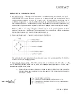
 

b.   

Signal Attenuation: 

Similar to the input voltage attenuation discussion, the resistance 

in  the  output  leads  will  also  cause  attenuation  of  the  output  signal.  The  reduced 
sensitivity is calculated as follows: 


E

O    

= sensitivity into an infinite load (from Cal. Cert.) 


E

OL  

= loaded output sensitivity 

R

O    

= output bridge resistance (from Cal. Cert.), including 

cable. 
R

L    

= load resistance 

R

CO 

= resistance of the spliced output wire 


c.   

Cable Capacitance

: Long cable leads act as an RC filter, which can cause significant 

attenuation of high frequencies. A rough calculation for the cut-off frequency of such 
a filter is as follows: 


fc = cut-off frequency, in Hertz (-3 dB)


R  = output resistance, in Ohm 
C  = cable capacitance, in Farad 


In general, the above effects are insignificant when cable length is 20 feet (6 meters) or less. The 
effects  discussed  in  sections  (a)  and  (b)  above  are  typically  accounted  for  in  any  factory 
calibration,  so  they  must  only  be  considered  when  longer  extension  cables  are  installed  by  the 
customer. Contact Applications Engineering for more information, if required. 

Summary of Contents for 727

Page 1: ...IM727 Rev A Page 1 of 9 INSTRUCTION MANUAL For Model 727 PIEZORESISTIVE DROP TEST ACCELEROMETERS IM727 Revision A 07 10 13 ...

Page 2: ... addition to being undamped the 727 series has no mechanical stops maximizing both bandwidth and amplitude linearity Its undamped characteristic allows it to be used in applications where the peak acceleration is known and there is not a significant amount of out of band energy that could cause enough resonance excitation to exceed the overrange limit of the accelerometer Due to the severe environ...

Page 3: ...does occur it will typically result in a large shift in the zero measurand output ZMO If ESD damage is sufficiently high complete accelerometer failure is likely showing up as an extremely large ZMO or an open leg of the Wheatstone bridge INITIAL CHECKOUT Upon receipt the accelerometer should be checked to ensure that it was not damaged in transit A simple resistance test is a quick way of verifyi...

Page 4: ...HANDLING The 727 series of drop test accelerometers are supplied with integral cables which are terminated in pigtails The user can select an appropriate end connector There are two important considerations regarding the integral cable when installing the accelerometer First since the cable will be exposed to the same high level shocks as the accelerometer care needs to be taken to prevent damage ...

Page 5: ...oresistive accelerometers including the 126 136 and 4430A Contact Applications Engineering to discuss your specific signal conditioning needs 2 Power and Signal Leads The cable leads are assigned as follows The cable shield is not connected to the accelerometer case It is recommended that the shield be connected to the power supply ground 3 Cable Length Considerations The 727 accelerometers are ca...

Page 6: ...nput voltage attenuation discussion the resistance in the output leads will also cause attenuation of the output signal The reduced sensitivity is calculated as follows EO sensitivity into an infinite load from Cal Cert EOL loaded output sensitivity RO output bridge resistance from Cal Cert including cable RL load resistance RCO resistance of the spliced output wire c Cable Capacitance Long cable ...

Page 7: ... to the Fourier transform Although resonance excitation cannot always be avoided it possible for the user to take measures to reduce the amount of high frequency energy the accelerometer will be subjected to BANDWIDTH AND AMPLITUDE LINEARITY Because the 727 series is undamped and does not use mechanical over travel stops accurate measurements are permitted over a wide frequency and amplitude range...

Page 8: ...th and a solvent such as acetone Do not soak or immerse the unit in any solvent or water Do not use any sharp tool such as a screwdriver to remove dirt or contaminants Any temporary adhesives such as wax or cyanoacrylate used to mount the accelerometer should be cleaned with an appropriate solvent such as acetone RECALIBRATION As with any measuring device optimum accuracy is maintained by periodic...

Page 9: ...out the health of your accelerometer please contact Applications Engineering An Application Engineer will be able to discuss the health of your accelerometer in more detail and suggest if it is healthy needs recalibration or needs replacement Endevco maintains an accelerometer recalibration service with NIST traceability in the United States Endevco European Regional offices maintain accelerometer...

Reviews: