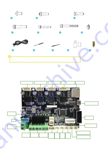
background image

Power Cord X 1

31

Nozzle Cleaner 

X 1

32

Cable Tie X 5

33

Memory Card and 
Card Reader X 1

34

Nozzle X 1

35

4 Printer Port Instructions

Mainboard Port Instructions


Note: The components above are for reference only. The actual product may vary.

M5x25 Socket Head 
Cap Screw with Spring 
Washer X 4

27

M4x20 Hexagon 
Flat Round Head 
Screw X 2

28

M5x45 Socket 
Head Cap Screw 
with Spring Washer X 4

29

M5 Ship-type 
Nut X 2

30

M5x8 Hexagon Socket 
Flat Head Screw X 4

24

M4x16 Socket Head Cap 
Screw with Spring Washer X 4

25

M4x18 Hexagon socket 
countersunk head screw X 2

26

TF

X-Axis Motor Port

Controllable 
fan port

Micro USB interface

Display port

Printhead thermistor 
interface
Hot bed thermistor 
interface

Reserved port of 
BL&CR_TOUCH

Normal fan 

port

Cable port 
for hot bed

Cable port 
for printhead

Filament 

Sensor

port

X-axis 

Limit 

Switch 

Port

Y-axis 

Limit 

Switch 

Port

Z-axis 

Limit 

Switch 

Port

Y-Axis Motor Port

Z-Axis Motor Port

Extrusion Motor Port TF Card Slot

Fuse

Power input
jack

Summary of Contents for Ender-3 E

Page 1: ... Ender 3 E To further improve your user experience you can find more about our devices via the following methods User manual Please find instructions and Assembe Installation Tutorial Video in the SD card provided with the printer ...

Page 2: ...ng materials and foreign objects on the guide rails This printer is provided with a safety protection mechanism Please do not manually move the nozzle or printing platform quickly while the printer is on otherwise the printer will automatically power off for protection Users should abide by the laws and regulations of the corresponding country and region where the equipment is located place of use ...

Page 3: ...9 M5 Ship type Nut X 2 30 M5x8 Hexagon Socket Flat Head Screw X 4 24 M4x16 Socket Head Cap Screw with Spring Washer X 4 25 M4x18 Hexagon socket countersunk head screw X 2 26 TF X Axis Motor Port Controllable fan port Micro USB interface Display port Printhead thermistor interface Hot bed thermistor interface Reserved port of BL CR_TOUCH Normal fan port Cable port for hot bed Cable port for printhe...

Page 4: ...from the bottom upwards and then tighten the screws D Rotate the base component by 180 again and tighten the screw on the right side Installation of power supply components and display A Fix the power supply component to the right profile of the Z axis with two M4x20 hexagonal cylindrical head spring washer combination screws note that the DIP switch faces backwards by this moment B Fix the display...

Page 5: ...itch Secure the Z axis limit switch to the outside of the left profile of the Z axis with 2 x M5 8 hexagon socket button head screws and 2 ship type nuts at a distance of 32 mm from the lowest part of the bottom profile Install the extrusion kit A Lock and secure the extrusion kit to the X axis profile with two M4X16 hexagonal button head spring washer combination screws B Then fix the pneumatic coupl...

Page 6: ...sher combination screws Installation of X axis adjusting component Loosen the screws of the X adjusting component slide the ship type nut along the profile slot and then pre lock it with a tool Install the X axis belt A Thread the belt through the pulleys of the motor and X adjusting component then snap the ends with the copper sleeves onto the printhead kit in the position shown B Adjust the posit...

Page 7: ... the X axis components A Place the top gantry profile on the profile to the left and right of the Z axis and lock it properly by aligning with the holes from top to bottom with four M5x25 hexagonal cylindrical head spring washer combination screws B Attach the 2 pcs of 20 profile end caps to each end of the top gantry profile Install the top gantry profile A Loosen the nut on the barrel thread the rack...

Page 8: ...calibration of 16 points and return to the home position again and then the levelling is complete 2 Enter Main menu click Motion click Probe Z Offset adjust Probe Z Offset make sure the distance between nozzle and platform is about the thickness of an A4 sheet of paper click Store Settings 3 Z axis height may be adjusted according to printing effect during the printing enter Main menu Tune Probe Z Off...

Page 9: ...filament is properly loaded 7 Loading the Filament Replacing the filament 1 When the printer is not printing A Heat the nozzle to 185 or higher wait for the filament in the nozzle to soften Then press and hold the extrusion handle to quickly extract the filament to prevent it from clogging in the heat break B Place the new filament onto the rack and repeat the steps in Section 7 Loading the Filament 2 ...

Page 10: ...d the file 7 Select the file Creality Slicer 4 8 2 Load The file name must only contain Latin letters and digits Chinese characters or special symbols must not be used Do not insert any levelling codes otherwise conflicts may be caused Note For details on using the software please refer to the slicing software user manual on the memory card Slicing tips Click the Random Information folder Slicing soft...

Page 11: ...trusion is smooth When the printer is powered on 1 The screen display and knob work properly The movements of the X Y and Z axes are smooth 2 The nozzle and hotbed heat up properly 3 The feed and return of the filament works properly 10 About the Printer 1 Material Barrel 2 Z axis left profile 3 Printhead kit 4 Rack 5 USB Port 6 TF Card Port 7 20 Profile end cap 8 Z axis right profile 9 Power supply m...

Page 12: ...rd 0 1mm 3D Creator Slicer Repetier Host Cura Simplify3D Input 100 120V 200 240V 50 60Hz Output DC 24V 100 C Layer Height Nozzle Diameter Accuracy Printing Material Supported Formats Printing Method FDM Modeling Technology Number of Nozzles Supported Slicing Software Power Specifications Total Power Hotbed Temperature 250 C Yes Nozzle Temperature Resume Printing Function Yes Filament Detection Yes ...

Reviews: