background image

EDM01-07: DAG 3.7G Card User Guide 

©2005 

17 

Version 7: May 2006 

Chapter 5: 

Synchronising Clock Time 

Overview 

The Endace DAG cards have sophisticated time synchronisation capabilities, 

which allow for high quality timestamps, optionally synchronized to an 

external time standard. 
The core of the DAG synchronisation capability is known as the DAG 

Universal Clock Kit (DUCK).  
An independent clock in each DAG card runs from the PC clock. The card’s 

clock is initialised using the PC clock, and then free-runs using a crystal 

oscillator.  
Each card's clock can vary relative to a PC clock, or other DAG cards. 


DUCK 

Configuration 


The DUCK is designed to reduce time variance between sets of DAG cards or 

between DAG cards and coordinated universal time [UTC].   
You can obtain an accurate time reference by connecting an external clock to 

the DAG  card using the time synchronisation connector. Alternatively you 

can use the host PCs clock in software as a reference source without any 

additional hardware. 
Each DAG card can also output a clock signal for use by other cards. 


Common 

Synchronization 


The DAG card time synchronisation connector supports a Pulse-Per-Second 

(PPS) input signal, using RS-422 signalling levels.  
Common synchronisation sources include GPS or CDMA (cellular telephone) 

time receivers.   
Endace also provides the TDS 2 Time Distribution Server modules and the 

TDS 6 units that enable you to connect multiple DAG cards to a single GPS 

or CDMA unit.  
For more information please refer to the Endace website at 

http://www.endace.com/accessories.htm

 , or the 

TDS 2/TDS 6 Units 

Installation Manual


Summary of Contents for DAG 3.7G Series

Page 1: ......

Page 2: ...39 0540 Fax 64 7 839 0543 Americas Endace USA Ltd Suite 220 11495 Sunset Hill Road Reston Virginia 20190 United States of America Phone 1 703 382 0155 Fax 1 703 382 0155 Europe Middle East Africa Enda...

Page 3: ...d Materials The product that this manual pertains to may include extra components and materials that are not essential to its basic operation but are necessary to ensure compliance to the product stan...

Page 4: ...EDM01 07 DAG 3 7G Card User Guide Version 7 May 2006 2005...

Page 5: ...ter 3 Configuring the Card 7 Introduction 7 Engaging Failsafe Relays 7 LEDs and Inputs 7 Configuration Utility 8 Default Configuration 8 Interface Statistics 10 Chapter 4 Capturing Data 13 Starting a...

Page 6: ...1 07 DAG 3 7G Card User Guide Version 7 May 2006 ii 2005 Table of Contents cont Chapter 6 Data Formats 25 Overview 25 Generic Header 25 Type 2 Record 26 Chapter 7 Troubleshooting 27 Reporting Problems...

Page 7: ...for your specific network requirements Running a data capture session Synchronising clock time Data formats You can also find additional information relating to functions and features of the DAG 3 7G...

Page 8: ...Installation Guide EDM 04 02 Windows Software Installation Guide Other Systems For advice on using an operating system that is substantially different from either of those specified above please cont...

Page 9: ...series card interfaces and fed through framers into the Xilinx FPGA This FPGA contains an Ethernet processor and the DUCK timestamp engine Because of close association of the components packets are ti...

Page 10: ...e failsafe feature of the DAG 3 7GF there are some advantages to using a straight through cable rather than a cross over one The DAG card captures all packets received on each port similar to a NIC in...

Page 11: ...M 04 02 Windows Software Installation Guide as appropriate which are included on the CD shipped with the DAG card Inserting the DAG Card To insert the DAG card in the PC follow the steps described bel...

Page 12: ...ernet The standard specifies a maximum cable length of 100 metres for 10Base T 100 BaseTX and 1000Base T operation over unshielded twisted pair CAT5E or better cable By default DAG 3 7G card automatic...

Page 13: ...ne forwarding applications to reconnect the two ports in case of power failure When the relays are in this state the ports are not connected to the physical layer devices on the card To use the card i...

Page 14: ...second More details about the meaning of the various parameters options are supplied through the help page dagthree h as well as via the manual page Default Configuration Before configuring the card f...

Page 15: ...ed out to the slen length Avoid large values of slen in fixed length mode as short packets arriving will produce large padded records wasting bandwidth and storage space rxsplit Send data from Port A...

Page 16: ...rr Ethernet Symbol Error Count Interface Statistics cont Example The following example is for a card with no valid input dagthree d dag0 si Spd Lnk FD Neg JB MA RF Err Spd Lnk FD Neg JB MA RF Err 1000...

Page 17: ...0 1 0 0 10 1 1 1 0 0 0 0 10 1 1 1 0 1 0 0 10 1 1 1 0 0 0 0 10 1 1 1 0 1 0 0 10 1 1 1 0 0 0 0 If the RF or JB bits are 1 s this indicates a problem with the network link This may or may not be related...

Page 18: ...EDM01 07 DAG 3 7G Card User Guide Version 7 May 2006 12 2005...

Page 19: ...view As the DAG 3 7T card captures packets from the network link it writes a record for each packet into a large buffer in the host PC s main memory Avoiding Packet Loss To avoid packet loss the user...

Page 20: ...is usually sufficient however if you do need to increase the amount of reserved memory please contact Endace customer support at support endace com for more information The dsize option sets the amou...

Page 21: ...mitting You can capture received traffic while transmitting Capture programs such as dagsnap dagconvert and dagbits can be used while dagflood is sending packets Configuring DAG card for transmission...

Page 22: ...C CPU and memory performance dagfwddemo Program The dagfwddemo program is provided as a demonstration of how this can be achieved This program forwards packets bidirectionally applying a user supplied...

Page 23: ...ween DAG cards and coordinated universal time UTC You can obtain an accurate time reference by connecting an external clock to the DAG card using the time synchronisation connector Alternatively you c...

Page 24: ...is allows an ultimate resolution of 2 32 seconds or approximately 233 picoseconds The ERF timestamp allows you to find the difference between two timestamps using a single 64 bit subtraction You do no...

Page 25: ...DAG device K timeout sync timeout in seconds default 60 l threshold health threshold in ns default 596 Option default RS422 in none out none None in none out rs422in RS422 input hostin Host input unu...

Page 26: ...Failures 0 Resyncs 0 error Freq 30ppb Phase 15ns Worst Freq 2092838ppb Worst Phase 33473626ns crystal Actual 100000023Hz Synthesized 67108864Hz input Total 225 Bad 0 Singles Missed 1 Longest Sequence...

Page 27: ...tus Synchronised Threshold 11921ns Failures 0 Resyncs 0 error Freq 1836ppb Phase 605ns Worst Freq 143377ppb Worst Phase 88424ns crystal Actual 49999347Hz Synthesized 16777216Hz input Total 87039 Bad 0...

Page 28: ...u Apr 28 14 48 34 2005 dag No active input Free running Note The slave card configuration is not shown as the default configuration will work Synchronising with Host To prevent the DAG card clock time...

Page 29: ...ried on circuit A and the serial packet is connected to the B circuit Pin Assignments The 4 pin RJ11 connector pin assignments are shown below 1 Channel A 2 Channel B 3 Channel B 4 Channel A Ethernet...

Page 30: ...EDM01 07 DAG 3 7G Card User Guide Version 7 May 2006 24 2005...

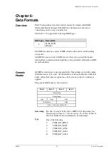
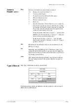
Page 31: ...and splitting to be performed arbitrarily on ERF record boundaries Generic Header All ERF records share some common fields Timestamps are in little endian Pentium native byte order All other fields a...

Page 32: ...value of 0 indicates the record was received from the host In the XScale Tx hole a value of 1 tells the ERF Mux to direct packets to the line A value of 0 directs packets to the host rlen Record lengt...

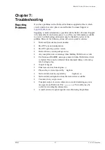
Page 33: ...number Host PC type and configuration Host PC operating system version DAG software version package in use Any compiler errors or warnings when building DAG driver or tools For Linux and FreeBSD mess...

Page 34: ...EDM01 07 DAG 3 7G Card User Guide Version 7 May 2006 28 2005...

Reviews: