background image

14   |   

Encore 18x6

 Sitdown Model User Guide

Machine Part Names

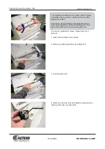
(Please note: the takeup lever guard has been removed for a clear view for pictures only.  Never run 
the machine without the guard in place. Extreme head injury may occur.)

This is a diagram of the side of your long arm machine.  The front of the machine faces the 
belly bar.  The back of your machine has the electrical outlet and stitch regulator plugs.  The 
numbers have been assigned in threading order.

1.

Upper Thread Guide

(Note: some machines do not have this)

2.

Three Hole Thread Guide

3.

Tension Disc

4.

Check Spring

5.

Silver Angle Bracket

6.

Thread Guide

7.

Take Up Lever

8.

Thread Guide

9.

Thread Guide

10.

Thread Eyelet Above the Needle

11.

Needle

Summary of Contents for sitdown

Page 1: ...sitdown model User Guide ...

Page 2: ......

Page 3: ...ion Release Lever 7 How Do I Adjust the Height of the Hopping Foot 7 Routine Cleaning and Oiling 8 Bobbin Winder and Bobbins 9 Machine Part Names 12 Threading Overview 13 How Do I Thread the Machine 13 How Do I Change the Needle 16 How Do I Make Adjustments to Make the Perfect Stitch 17 Tension Tension Tension 18 Trouble Shooting Checklist ...

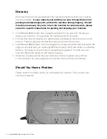
Page 4: ... parts for five years The machine must be cleaned and oiled regularly according to the instructions in this manual Failure to properly maintain the machine will void this warranty Your Encore 18x6 Sitdown must be plugged into a surge protected electrical outlet We highly recommend using an Uninterrupted Power Supply UPS also known as a Battery Backup This helps to ensure that you are getting a reg...

Page 5: ...trim the cord so that it will reach the outlet on top of the power box This outlet is also where you will find the plug for your lamp Open your plug by pulling on the silver tab and open the plug Trim the wires flush with enough to reach the outlet on the top of the power box Lay the wires in the space provided in the plug and close the plug Caution Before you close make sure that you do not have ...

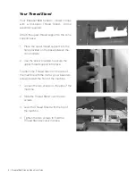
Page 6: ...ovided on the base between the cone holders 2 Use the screw provided to secure the upper thread support into place To attach the Thread Stand on the side of the machine with the motor you will see two screws toward the front of the machine 1 Loosen the two screws on the side of the machine 2 Slide the Thread Stand over the two screws 3 Level the Thread Stand with the top of the machine 4 Tighten t...

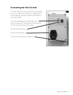
Page 7: ...om side of the box Plug the Foot Control plug into the jack provided on the base of the power supply Turn the sewing speed controller dial to the right to increase the motor speed turn the dial to the left to decrease the motor speed Needle position buttons Power cord connection Foot control connection is under here ...

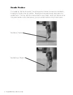
Page 8: ...ake one full rotation bringing the needle to the up position Pressing the foot pedal slowly will position the needle down This may take some test presses to get it down and to get the feel for the foot pedal needle control Alternatively you can use the buttons on the control panel Needle Up Position Needle Down Position ...

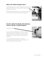
Page 9: ...ches will be huge loops How Do I Adjust the Height of the Hopping Foot for Thicker or Thinner Batting Adjustment Screw If you are quilting on batting that is thicker than normal you might need to raise the Hopping Foot Loosen the screw holding the Hoping Foot on slide the foot up for thicker or down for thinner Be sure to tighten the screw after your adjustment The normal height of the Hopping Foo...

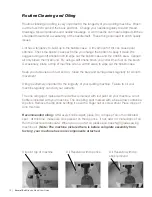
Page 10: ...ab to wipe out the bobbin case Keep your table clean of dust and oil Clean the bars and carriage deck regularly for smooth movement Oiling is extremely important to the longevity of your quilting machine Failure to oil your machine regularly can void your warranty The one oiling spot marked with red arrow is marked with red paint on your machine An oil bottle is included with your machine The one ...

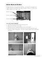
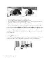
Page 11: ...in poor stitch quality Bobbin Thread Bobbin Thread Guide Bobbin Winder How do I wind a Bobbin 1 Insert an empty bobbin on the Bobbin Winder spindle 2 Place a cone of thread on the holder 3 Bring the thread up through the guide over the cone of thread 4 Insert the thread through the top guide hole then around the tension disc and through the bottom thread guide This tension is for the bobbin tensio...

Page 12: ...t have thread in the needle to prevent jams Also remove the bobbin and bobbin case to prevent damage NOTE There is no way to stop the needle from moving while the bobbin is winding The bobbin will fill until the trip mechanism is pushed out by the thread It will then disengage the wheel The bobbin should fill to just below the rim Having the bobbin too full will cause tension problems Bobbing Fill...

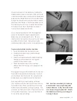
Page 13: ... remove the screw as it is very small and difficult to find if lost Remember righty clockwise tighty lefty counter clockwise loosey To place the bobbin into the machine 1 Insert the bobbin into the bobbin case 2 Holding the bobbin case pull the thread through the slot 3 Draw the thread down and under the spring making sure the thread is in the highest position of the bobbin case 4 Place the bobbin...

Page 14: ...the side of your long arm machine The front of the machine faces the belly bar The back of your machine has the electrical outlet and stitch regulator plugs The numbers have been assigned in threading order 1 Upper Thread Guide Note some machines do not have this 2 Three Hole Thread Guide 3 Tension Disc 4 Check Spring 5 Silver Angle Bracket 6 Thread Guide 7 Take Up Lever 8 Thread Guide 9 Thread Gu...

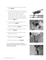
Page 15: ...achine without the guard in place Extreme head injury may occur How Do I Thread the Machine 1 Place a cone of thread on the thread holder Figure 1 2 Pull thread through the eyelet above the cone of thread Make sure the eyelet is directly above the thread cone Figure 1 3 Thread the upper thread guide as shown in picture Figure 2 Figure 1 Figure 2 ...

Page 16: ... tension disc Figure 4 6 Thread runs under silver angle bracket See picture for details Figure 4 7 Bring the thread up through the thread guide just above the check spring Figure 4 8 Take the thread through the take up lever from back to front Figure 5 9 Bring the thread down through the two thread guides on the left side 10 Bring the thread through the thread eyelet directly above the needle Figu...

Page 17: ...ound behind the needle to pick up the thread The scarf has to be there to provide a way for the hook to get between the needle and the thread in order to pick up the thread Place the new needle up in the slot making sure the needle is up in the needle bar as far up as it will go Make sure the scarf is facing the right of your machine Tighten the screw on the needle bar while holding the needle up ...

Page 18: ...s a home sewing machine except the quilter is the feed dog moving the machine head over the fabric The hopping foot presses the fabric together tighter and quicker than a home sewing machine presser foot because the fabric must be able to slide between the foot and the needle plate as the machine is sewing This means that the machine is moving while the needle is in the fabric The worst thing for ...

Page 19: ...ality Lower and the quilt will create a drag on your machine s movement Look at your bobbin A sloppy wound bobbin will not create a good stitch Make sure that the threads on the bobbin are snug and evenly wound Check to see if there is a piece of lint in the bobbin case Tension Trouble Shooting Checklist Is the side tension lever down Have I oiled my machine regularly Is the quilt too tight on the...

Page 20: ...ad while large and small stitches in regulated mode means the encoders are not picking up the signal of your movements because of lint or thread stopping or slowing the reading First check to see that your machine is threaded correctly Look at the check spring Does the thread lay in the check spring When properly threaded the check spring will move up and down as the machine is stitching and the t...

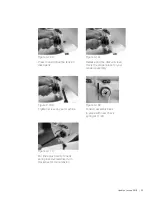
Page 21: ...ck Spring This series of photos will help Tension assembly with broken spring old tension knob Broken Spring Figure 3 84 Tension assembly with good spring new tension knob Figure 3 85 Screw on inside of machine loosen only DO NOT REMOVE Figure 3 86 Remove assembly from machine Be careful with release pin Figure 3 87 ...

Page 22: ...y out of machine DO NOT LOSE PIN Figure 3 89 PIN Machine with tension assembly removed Figure 3 88 Loosen screw only DO NOT REMOVE Figure 3 90 Remove tension assembly from barrel Figure 3 91 Tension assembly and barrel Figure 3 92 Remove spring Figure 3 93 ...

Page 23: ...23 New spring in place Figure 3 99 Twist while inserting the new spring Figure 3 98 Insert the new spring Figure 3 97 New spring This tail is what was broken Figure 3 96 Spring removed Figure 3 95 Spring removal Figure 3 94 ...

Page 24: ...ck into your machine Figure 3 104 Tighten screw Make sure the pin is still there Figure 3 103 Give the tension assembly a twist until you feel resistance on the check spring Figure 3 102 Insure that you are all the way in Figure 3 101 Insert the tension assembly back into the barrel REMEMBER DO NOT LOSE THE PIN Figure 3 100 ...

Page 25: ...e with new check spring at 11 00 Figure 3 109 For fine adjustment of check spring insert screwdriver turn clockwise for more tension Figure 3 110 Press in and notice the tension disk opens Figure 3 106 Release and the disk will close this is the proper place for your tension assembly Figure 3 107 ...

Page 26: ...machine You will also need to remove the three face plate screws The protecting flange of the position bracket A should be engaged in the notch B of the bobbin case holder D is the set screw to adjust hook timing The photo on the right is the actual machine as shown in the drawing The drawing and the photo show correct timing ...

Page 27: ...o its lowest position At the lowest position turn the hand wheel to raise the needle 2 5 mm 1 8 Hook point should be just above the eye of the needle Hook Point This picture shows the needle bar and the hook point at the proper location after needle bar rise Note If the hook point is not in this location reference drawing 31 Loosen screw D There are three screws At this point the rotating hook can...

Page 28: ...1 800 401 8151 www sewingmachinesplus com com Proud to be a LEADInG manufacturer of long arm quilters in the U S ...

Reviews: