EM TEST (Switzerland) GmbH
PFM 200N100.1
User’s Guide
Ver. 1.12
10 / 43
3.4.
Installation
3.4.1. Unpacking
Before shipment, the device is carefully tested and packed on a one-way pallet. Every box is marked with a
warning notice and packing list.
Before installation, check the contents the delivery contents for transport damage. Check that the packaging is in
good condition and ensure that the device does not exhibit any mechanical damage. If this is the case, please
immediately inform EM Test or their authorized representative before putting the device into operation.
3.4.2. Setup and Cabling the Test System
Control Cables
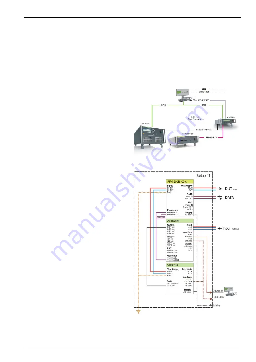
Figure 3.10 shows the typical usage of control cables
for the test system:
-
AutoWave
Controls the PFM
-
PFM 200N100.1
Dropout simulator
-
VDS 200Nx
DC source for powering the DUT
AutoWave.control is required in order to operate the
PFM 200N100.1. This software contains all the test
routines for testing with the PFM 200N100.1
Figure 3.10: Control Cables
Cabling for the System
Figure 3.11 shows all connections necessary for the
PFM 200N100.1, AutoWave und VDS:
Cable List
:
Computer
– AutoWave
GPIB / IEEE488 or
Ethernet
AutoWave - VDS200N100
IEEE 488
IEEE488
CH 1 BNC
0-10V BNC
AutoWave - PFM 200N100.1
Framebus OUT Framebus IN
15 Pin D-Sub
VDS200Nx - PFM 200N100.1
DUT +
PF1 IN +
DUT power, 100A max.
DUT -
PF1 IN -
DUT power, 100A max.
PFM 200N100.1
Framebus OUT
Framebus Termination
Earth Connection: VDS 200Nx and PFM 200N100.1
Mains power:
to all devices (1ph / 3ph)
Figure 3.11: Cabling for the System with a PFM 200N100.1


