background image

40946-0-1019

Page 16

DVB-1 For Direct Vent Wall Furnaces DV210 and DV215

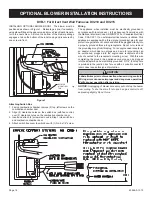
INSTALLING OPTIONAL BLOWER DVB-1.  The blower must be 

positioned as shown in Figure 1.  Relocate gas line, if necessary, 

using elbow fitting at the gas valve, and move Piezo Spark Genera

-

tor to the next screw.  A slot on the bottom of the blower package 

engages a tab on the bottom of the inner casing and is secured by 

one screw in front.

BLOWER

MOUNTING

TAB

Figure 1

Attaching Switch Box

1.  Facing combustion chamber, remove (2) top, left screws on the 

combustion chamber door.

2.  Align (2) clearance holes on the switch box (with fan control) 

over (2) clearance holes on the combustion chamber door.

3.  Insert and attach (2) screws removed in Step 1 into switch box 

and combustion chamber door. 

4.  Attach switch box cover to switch box with (1) No. 8 x 1/4" screw.

OPTIONAL BLOWER INSTALLATION INSTRUCTIONS

Wiring

The appliance, when installed, must be electrically grounded in 

accordance with local codes or, in the absence of local codes, with 

the National Electrical Code, ANSI/NFPA 70 or Canadian Electrical 

Code, CSA C22.1, if an external electrical source is utilized. This 

appliance is equipped with a three-prong [grounding] plug for your 

protection against shock hazard and should be plugged directly into 

a properly grounded three-prong receptacle.  Do not cut or remove 

the grounding prong from this plug.  For an ungrounded receptacle, 

an adapter, which has two prongs and a wire for grounding, can 

be purchased, plugged into the ungrounded receptacle and its 

wire connected to the receptacle mounting screw.  With this wire 

completing the ground, the appliance cord plug can be plugged 

into the adapter and be electrically grounded.  A 7/8" (22mm) hole 

is provided in the junction box for use with a conduit connector if 

local codes require this type of protection.

CAUTION

Label all wires prior to disconnection when servicing controls.  

Wiring errors can cause improper and dangerous operation. 

Verify proper operation after servicing.


NOTICE:

 Unplugging of blower accessory will not stop the heater 

from cycling. To shut heater off, turn knob on gas control to off, 

depressing slightly. Do not force.

Summary of Contents for DV210SGXLP-2

Page 1: ...try to light any appliance Do not touch any electrical switch do not use any phone in your building Leave the building immediately Immediately call your gas supplier from a neighbor s phone Follow the...

Page 2: ...Specifications 6 Gas Supply 7 Clearances 8 Installation Instructions 8 9 Lighting Instructions 10 Maintenance 12 Pilot Flame Characteristics 13 Main Burner Flame Characteristics 13 Troubleshooting 13...

Page 3: ...a qualified service person More frequent cleaning may be required due to ex cessive lint from carpeting bedding materials etc It is imperative that control compartments burners and circulating air pas...

Page 4: ...adsorb or absorb onto or into walls masonry and other materials and fabrics in a room That will take some of the odorant out of the gas reducing its odor intensity Propane Gas may stratify in a closed...

Page 5: ...ide detector as required in accordance with the above provisions shall comply with NFPA 720 and be ANSI UL 2034 listed and IAS certified 3 SIGNAGE A metal or plastic identification plate shall be per...

Page 6: ...g of equipment shall be performed only by a qualified agency The term qualified agency means any individual firm corporation or company which either in personorthrougharepresentativeisengagedinandisre...

Page 7: ...n while all other appliances connected to the venting system are not in operation 1 Seal any unused openings in the venting system 2 Inspect the venting system for proper size and horizontal pitch as...

Page 8: ...test should be made Never use an exposed flame to check for leaks Appliance must be disconnected from piping at inlet of control valve and pipe capped or plugged for pressure test Never pressure test...

Page 9: ...m screw provided On sheet rock wall secure furnace support bracket with 1 toggle bolt provided 64mm 13mm Figure 4 INSTALLATION INSTRUCTIONS 1 In selecting a location for installation it is necessary t...

Page 10: ...side wall plate Use additional caulking to correct uneven wall surface such as clapboard 3 Attach 5 127mm diameter air inlet tube onto the collar of air drop assembly Attach caulked outside wall plate...

Page 11: ...ockwise to ON 12 Replace control access panel front panel 13 Turn on all electric power to the appliance if applicable 14 CAUTION Pilot access cover must be kept tightly closed during operation TO TUR...

Page 12: ...orifice threads when replaced 5 To remove the entire gas valve the nut holding the orifice fitting to the chamber must be removed and the gas supply to the valve disconnected After this the valve and...

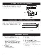
Page 13: ...Replace 3 Yellow pilot flame a Obstruction at pilot orifice b Clean and properly size orifice 4 Pilot and main burner go out during normal operation a Check millivolts b Check for proper size of pilot...

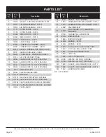
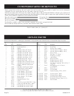
Page 14: ...P8658 BURNER ORIFICE DV215 PROPANE 13 P104 ORIFICE FITTING 14 R1055 ELECTRODE AND WIRE 15 R12797 MANIFOLD 16 R12791 GAS VALVE 7000 MVRLC NATURAL 16 R12792 GAS VALVE 7000 MVRLC PROPANE 17 R12795 PILOT...

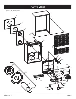
Page 15: ...40946 0 1019 Page 15 MODEL DV 210 SHOWN 1 2 3 4 5 6 7 8 9 10 13 12 17 11 18 19 14 15 21 20 16 22 23 25 24 26 27 31 28 29 30 PARTS VIEW MODEL DV 210 SHOWN...

Page 16: ...bsence of local codes with the National Electrical Code ANSI NFPA 70 or Canadian Electrical Code CSA C22 1 if an external electrical source is utilized This appliance is equipped with a three prong gr...

Page 17: ...l Furnaces DV210 and DV215 OPTIONAL BLOWER INSTALLATION INSTRUCTIONS Oiling the Motor Oiling holes are provided on each end of the motor for oiling The blower should have five drops of 20 motor oil ev...

Page 18: ...se and can be ordered by your Service Person or Dealer Proof of purchase is required for warranty parts All parts listed in the Parts List have a Part Number When ordering parts first obtain the Model...

Page 19: ...le cancelled check or payment record should be kept to verify purchase date and establish warranty period Ready access to the appliance for service What Is Not Covered Damages that might result from t...

Page 20: ...ww empirecomfort com Empire Comfort Systems Inc Belleville IL If you have a general question about our products please e mail us at info empirecomfort com If you have a service or repair question plea...

Page 21: ...endido 9 DV 781 Ensamblaje Cubierta Agujero Encendido 10 DV 064 L mina Cubierta Agujero Encendido 11 852098 Tuerca para Tenedor Inyector 12 742134 Inyector Quemador DV 210 Natural 12 742133 Inyector Q...

Page 22: ...40946 0 1019 Page 17 VISTA DE PARTES MODEL DV 210 SHOWN 1 2 3 4 5 6 7 8 9 10 13 12 17 11 18 19 14 15 21 20 16 22 23 25 24 26 27 31 28 29 30 MODELO DV 210 MOSTRADO...

Page 23: ...ran los c digos locales de protecci n CUIDADO Marque todos los cables antes de la conexi n cuando le d servicio a los controles Errores atribuidos a conexi n de cables pueden causar una operaci n inco...

Page 24: ...con el artefacto Se debe conservar un comprobante de venta un cheque cancelado o un registro de pago para verificar la fecha de compra y establecer el per odo de garant a Acceso f cil al artefacto par...

Page 25: ...Comfort Systems Inc Belleville Illinois Si Ud tiene una pregunta general acerca de nuestros productos por favor env enos un correo al info empirecomfort com Si Ud tiene una pregunta de servicio o de r...

Reviews: