


11
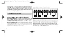
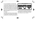
2.6. Wiring
IMPORTANT NOTICE! Disconnect the positive battery ter-
minal („+12 V“) before any wiring work!
Wiring Tips!
Use rubber grommets when running cables through any metal or sharp pla-
stic, to prevent accidental shorting or shearing. Make sure that the cables
do not interfere with normal operation of the vehicle. Especially the signal
cables (RCA interconnects) should be kept far away from any potential
sources of electrical interference e.g. electronic vehicle management systems
(engine computers, relays etc.) fuel pumps, wiring harnesses etc.
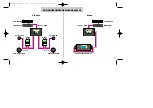
2.6.1 Carefully run the audio signal and remote switching ca-
ble(s) from the head-unit to the amplifier.
The audio signal cables
should be routed completely separate from the power cables. Use only double
or triple shielded quality cables! Connect the remote (turn on/turn-off) lead
to the respective outputs of the head-unit and the amplifier. If your head unit
does not have a remote lead, you may also use the antenna remote option.
Now you connect the audio cable to the respective outputs on the head-unit
and inputs on the amplifier.
2.4 Location of the Amplifier
The location of the power amplifier should be well selected. In the interest
of passive driver and passenger safety, solid mounting of the amp unit is cru-
cial. The actual mounting surface should be completely flat. Any mounting
position allowing for a good air stream across the cooling fins of the ampli-
fiers heatsink will improve cooling (at low impedance loads!) and long-term
stability dramatically. Make sure there is no wiring harness, fuel tank etc. be-
hind or below the mounting surface, that may be damaged by the drilling of
the holes for the amplifier mounting screws. After installation, there should be
a clearance of at least 5 cm on all sides including the top of the amplifier heat-
sink. Make sure the unit is not exposed to direct sunlight, humidity, water, oil
or other fluids that may enter the amplifier. It is also recommended that the
location of the amplifier allows easy access of all side panel controls.
2.5 Mounting the Amplifier
Once the location for the amplifier is defined, use the unit as a template for
the marking of the mounting holes with a pencil or felt-tip. The mounting
holes should be pilot-drilled using a 2,5 mm or 3 mm drill. For the actual
mounting, the supplied rubber grommets have to be pressed into the moun-
ting holes of the amplifier, before inserting the supplied mounting screws. The
rubber grommets protect the amplifier from electrical ground-loops that can
easily result in audible hum!
EA2190490 Manual neu 31.07.2000 19:02 Uhr Seite 11


