background image

19

Min

Min

Min

Min

Min

Default

Default

Default

Default

Default

Unit

Unit

Unit

Unit

Unit

Max

Max

Max

Max

Max

0

0

0

0

0

1

1

1

1

1

0

0

0

0

0

122

122

122

122

122

0

0

0

0

0

21

62

12

13

14

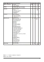
The same as Configurable Output-1 options

The same as Configurable Output-1 options

The same as Configurable Output-1 options

The same as Configurable Output-1 options

The same as Configurable Output-1 options

CONF. OUTPUT-2 (

Out

puts->Conf. output-2

)

CONF. OUTPUT-3 (

Out

puts->Conf. output-3

)

CONF. OUTPUT-4 (

Out

puts->Conf. output-4

)

CONF. OUTPUT-5 (

Out

puts->Conf. output-5

)

CONF. OUTPUT-6 (

Out

puts->Conf. output-6

)

Polarity

Polarity

Polarity

Polarity

Polarity

Function

Function

Function

Function

Function

0- Normally Open (Close To Activate)
1- Normally Close (Open To Activate)

0- Normally Open (Close To Activate)
1- Normally Close (Open To Activate)

0- Normally Open (Close To Activate)
1- Normally Close (Open To Activate)

0- Normally Open (Close To Activate)
1- Normally Close (Open To Activate)

0- Normally Open (Close To Activate)
1- Normally Close (Open To Activate)

Min

Default

START TIMERS (

Timers->Start timers

)

Max

Mains Transient Delay

Remote Start Delay 

Pre-Heat

2.0

Pre-Heat Bypass

0.0

20.0

4

0

3600

3

0

250

0

0

250

Safety On Delay

5

0

99

Horn Duration 

60

0 (dis)

999

Charge Excitation Time 

15

0 99(cont)

Cooling Fan Time

180

0

250

Remote start delay

Pre-heat
Pre-heat bypass

Safety on delay

Horn duration

Chg. excitation time
Cooling fan time

Mains transient delay

Mains Fail Start Delay

0

0

9999

Mains fail start dely

Unit

Sec

Min

Sec
Sec

Sec

Sec
Sec
Sec

Sec

Idle Mode Time (Smoke Limiting)

dis

3600

Idle mode time

Idle Mode Time Off (Smoke Limiting Off)

Idle mode time off

Sec
Sec

0 (dis)

0

250

5

4.2.7 Timers

Warmup Time

3

0

250

Warming up time

Sec

Min

Default

STOPPING TIMERS (

Timers->Stopping timers

)

Max

Remote Stop Delay
Cooling Time

4

0

250

60

0 (dis) 3600

Fail To Stop Time

30

15

99

Remote stop delay
Cooling time

Fail to stop delay

Unit

Sec
Sec
Sec

Mains Return Delay

5

0 3600

Mains return delay

Sec

Note: 

dis = disable            cont = continuous

Summary of Contents for TRANS-MINIAMF

Page 1: ...e repeated a programmed number of times or until successful The unit monitors generator operation and gives warning of any faults that are detected If a fault is detected the unit shuts down the engine and shows the failure message on the LCD display 1 1 General Specifications 1 2 Warranty EMKO Elektronik warrants that the equipment delivered is free from defects in material and workmanship This w...

Page 2: ...nstallation of this product please read the instruction manual and warnings below carefully 2 Installation Ýçindekiler 2 1 Unit Configuration Ýçindekiler 2 2 Panel Mounting The unit is designed for panel mounting Fixing is by two screw fixings 1 Insert the unit in the panel cut out from the front 2 Insert the fixings in the slotted at the corners of the unit and tighten the fixing screws to secure...

Page 3: ...5 BATTERY 16 FUSE 5 3 1 21 MPU Emergency Stop or Configurable Input 1 27 26 25 8A 8A 30 2 24 29 1 L1 GENERATOR Max 300VV MAINS L2 L3 N M LOAD G L1 L2 L3 N El c r c l nte lock e t i a i r Me hanica in rl k c l te oc 4 3 Max 300VV Mains Contactor Relay Generator Contactor Relay FUSE 1 FUSE 2 FUSE 3 FUSE 4 4 FUSE 1 FUSE 2 FUSE 3 FUSE 4 2A T FUSE 5 8A T FUSE 6 FUSE 7 8A T SCR 28 31 SCR L J1939 ECUs H ...

Page 4: ...0V V31 380V V3 220V Wait for start To exit from programming mode any time press Stop Reset button for 2 seconds MAINS V12 380V V1 220V V23 380V V2 220V V31 380V V3 220V Wait for start ü ü AUTO RESET Press Enter button for 2 seconds to access the menu options When the Enter button is pressed the parameters section is asked for accessing to parameters Program Language Event log AUTO RESET ü ü PROGRA...

Page 5: ...tdown delay time Generator Voltage Shutdown Delay Time GENERATOR VOLT LEVEL Generator Volt level 0 0 10 0 1 0 Sec 75 0 30 0 dis 75 0 75 0 Hz 30 0 dis Min Default Max Generator Under Frequency Pre Alarm Generator Under Frequency Pre Alarm Return Generator Over Frequency Shutdown Generator Over Frequency Pre Alarm Generator Over Frequency Pre Alarm Return 45 0 46 0 58 0 55 0 54 0 Generator Frequency...

Page 6: ... 59 23 59 23 59 23 59 23 59 23 59 23 59 23 59 H Min H Min H Min H Min H Min H Min H Min H Min H Min H Min H Min H Min H Min H Min 0 00 0 00 0 00 0 00 0 00 0 00 0 00 0 00 0 00 0 00 0 00 0 00 0 00 0 00 0 00 0 00 0 00 0 00 0 00 0 00 0 00 23 59 23 59 23 59 23 59 23 59 23 59 23 59 DISBL ENABL DISBL 9999 9999 9999 9999 9999 9999 kVA kVA kVA kVA 0 dis 0 dis 0 0 dis 0 dis 0 Min Default Max Generator Under...

Page 7: ...brk cls contact Transfer time Spring loading time Retry number Break open pulse time Sec Sec 1 250 0 5 0 5 Sec Sec Sec Sec Sec 3 5 1 250 1 250 Min Default Unit LCD DISPLAY System LCD display Max Language Selection Digital Contrast ENGLISH CHINESE 5 4 9 Contrast Language 1 Auto Scroll Time Auto Scroll Number Scroll Time For Error Messages 0 0 dis 250 Sec 3 11 2 1 250 Auto scroll number 2 Err mesg s...

Page 8: ...r freq reset Over freq trip Over freq reset Unit 600 60 dis 60 60 600 600 600 VV VV VV VV 60 dis Min Default Max Generator Under Voltage Shutdown Generator Under Voltage Pre Alarm Generator Under Voltage Pre Alarm Return Generator Over Voltage Shutdown Generator Over Voltage Pre Alarm 320 340 350 440 60 dis 600 60 600 420 400 Generator Over Voltage Pre Alarm Return VV VV Under volt shutdown Under ...

Page 9: ...r Under Power Pre Alarm Generator Under Power Pre Alarm Return Generator Over Power Shutdown Generator Over Power Pre Alarm dis 5 Generator Over Power Pre Alarm Return kVA kVA Under power shutdown Under power prealarm Under power reset Over power shutdown Over power prealarm Over power reset Unit Shutdown delay time Generator Power Shutdown Delay Time GEN POWER LEVEL Generator Power level 0 99 2 S...

Page 10: ...ator Frq En Dis Sens option gen freq ENABL ENABL DISBL 0 dis Sensing Opt Pickup En Dis Flywheel DISBL 1000 All Warnings Are Latched En Dis Sens opt pickup flywh 3 All warning are latch ENABL DISBL DISBL 3 Note These parameters are only available at Trans MiniAMF MPU dis disable Min Default Max Working Calendar Disable or Enable Working Calendar Work Start Time on Monday Working Calendar Work Stop ...

Page 11: ...Bus ECU Baud Rate 0 20 1 50 2 100 3 125 4 250 5 500 6 800 7 1 000 J1939 ECU Type Selection 0 Disable 1 Standard 2 Volvo EMS1 3 Volvo EMS2 4 Volvo EMS2b 5 Volvo EDC3 6 Volvo EDC4 7 Deutz EMR2 8 Deutz EMR3 9 Perkins 1300 10 Perkins ADEM3 11 Perkins ADEM4 Baud rate J1939 ECU type Device address Engine cont address Min Default Unit Max 0 7 4 11 0 0 255 17 0 255 0 kBaud ECU remote control Speed control...

Page 12: ...erator Followed By Shutdown After Cooling 4 Shutdown Alarm And Shutdown 2 0 2 0 0 dis 4 Amber warn activation Amber warn actions Sec J1939 Amber Warning Lamp Delay 2 0 250 Amber warn delay J1939 Amber Warning Lamp Activation 0 Active From Starting 1 Active From Safety On 2 Always Active J1939 Red Stop Lamp Actions 0 Disable 1 Warning Non Latching 2 Warning Alarm Only No Shutdown 3 Electrical Trip ...

Page 13: ...erval Force Engine Shutdown When Maintenance Is Due Engine Running Hour Lsb 5000 Engine Running Hour 0 dis 9999 Engine Running Hour Msb ENABL DISBL 0 0 255 DISBL 0 0 0 dis 12 6 0 255 0 14 Maint date interval Eng stop when maint Eng running hour lsb Eng running hour Eng running hour msb Running hour interval Unit Hour Month Maintenance Okay NO Maintenance okay YES NO Min Default Unit ENGINE GENERAL...

Page 14: ...Input Type 3000 90 0 3000 Conf AI low shutdwn Conf AI high prealr Conf AI high shutd 3 0 Not Used Disable 1 Digital NC 2 Digital NO 3 VDO 120 ºC 4 VDO 150 ºC 5 DATCON 6 MURPHY 7 PT100 8 User Configured 3 0 Not Used Disable 1 Digital NC 2 Digital NO 3 VDO OHM 10 180 4 VDO TUBE 90 0 5 US OHM 240 33 6 GM OHM 0 90 7 FORD 73 10 8 User Configured 0 dis 0 dis 0 dis 0 dis 0 dis 0 dis Oil Pressure Unit Oil...

Page 15: ... 4 Configurable Analog Input Point 5 11 29 47 65 82 100 117 134 151 184 291 197 134 97 70 51 38 29 22 15 10 30 50 70 90 0 0 0 0 0 0 0 0 0 0 0 0 0 0 0 0 0 0 0 0 0 0 0 0 0 1300 1300 1300 1300 1300 1300 1300 1300 1300 1300 1300 1300 1300 1300 1300 1300 1300 1300 1300 1300 1300 1300 1300 1300 1300 0 0 0 5 1 0 1 5 2 0 2 5 3 0 3 5 4 0 5 0 40 50 60 70 80 90 100 110 120 140 0 11 22 33 44 0 0 0 0 0 0 0 0 0...

Page 16: ...nput Point 6 Configurable Analog Input Point 7 Configurable Analog Input Point 8 Configurable Analog Input Point 9 Configurable Analog Input Point 10 110 130 150 170 190 0 0 0 0 0 1300 1300 1300 1300 1300 55 66 77 88 100 0 0 0 0 0 R R R R R 3000 3000 3000 3000 3000 Conf AI sender 6 Conf AI sender 7 Conf AI sender 8 Conf AI sender 9 Conf AI sender 10 Conf AI value 6 Conf AI value 7 Conf AI value 8 ...

Page 17: ...s Active If Select From List 0 Remote Start On Load 1 Remote Start Off Load 2 Auxiliary Mains Fail 3 Reserved 4 Reserved 5 Reserved 6 Simulate Auto Button 7 Simulate Test Button 8 Reserved 9 Simulate Start Button 10 Simulate Stop Button 11 Generator Closed Auxiliary 12 Generator Load Inhibit 13 Mains Closed Auxiliary 14 Mains Load Inhibit 15 Auto Restore Inhibit 16 Auto Start Inhibit 17 Panel Lock...

Page 18: ...CY PRE ALARM 56 GENERATOR LOW FREQUENCY SHUTDOWN 57 GENERATOR LOW VOLTAGE PRE ALARM 58 GENERATOR LOW VOLTAGE SHUTDOWN 59 GENERATOR STOPPING 60 GENERATOR OPEN BREAKER 61 HORN OUTPUT LATCHED 62 HORN OUTPUT PULSED 63 LAMP TEST 64 RESERVED 65 LOSS OF MAGNETIC PICK UP SPEED SIGNAL only available at Trans MiniAMF MPU 66 LOW TEMPERATURE 67 MAINTENANCE DUE ALARM 68 MAINS CLOSED AUXILIARY 69 MAINS FAILED T...

Page 19: ...Close To Activate 1 Normally Close Open To Activate 0 Normally Open Close To Activate 1 Normally Close Open To Activate Min Default START TIMERS Timers Start timers Max Mains Transient Delay Remote Start Delay Pre Heat 2 0 Pre Heat Bypass 0 0 20 0 4 0 3600 3 0 250 0 0 250 Safety On Delay 5 0 99 Horn Duration 60 0 dis 999 Charge Excitation Time 15 0 99 cont Cooling Fan Time 180 0 250 Remote start d...

Page 20: ... Default Unit CURRENT OFFSET User adjustment Current offset Max 0 20 Current I1 offset Current I1 Offset 20 AV Min Default Unit BATTERY CHRG GEN VOL User adjustment Battery chrg gen vol Max 0 0 5 0 5 0 Batt volt offset Gen chg volt offset Battery Voltage Offset Charge Generator Voltage Offset 5 0 5 0 VZ VZ Min Default Unit SENDER INPUTS OFFSET User adjustment Sender inputs offset Max 0 0 0 0 2 0 2...

Page 21: ...0 VAC Ph N 5 to 99 9 Hz Accuracy 1 FS Resolution 1 V Mains Frequency 5 to 99 9Hz min 20 VAC Ph N Accuracy 0 25 FS Resolution 0 1 Hz Generator Voltage Measurement 3 to 300 VAC Ph N 5 to 99 9 Hz Accuracy 1 FS Resolution 1 V Generator Frequency 5 to 99 9Hz min 20 VAC Ph N Accuracy 0 25 FS Resolution 0 1 Hz 5A Z Sender Measurement 0 to 1300 ohm accuracy 1 FS resolution 1 ohm Magnetic Pickup Input 35 t...

Page 22: ... very much for your preference to use Emko Elektronik products please visit our web page to download detailed user manual Your Technology Partner www emkoelektronik com tr 7 Order Information Trans MiniAMF Automatic GenSet controller with transfer switching Trans MiniAMF CAN Automatic GenSet controller with transfer switching CanBus J1939 ECU communication Trans MiniAMF MPU Automatic GenSet contro...

Reviews: