background image

Supply Input

of Device

2000V


V

Transistor Out

puts

RS 232

RS 485

Usb

2000V


V

15

00V


V

Ethernet

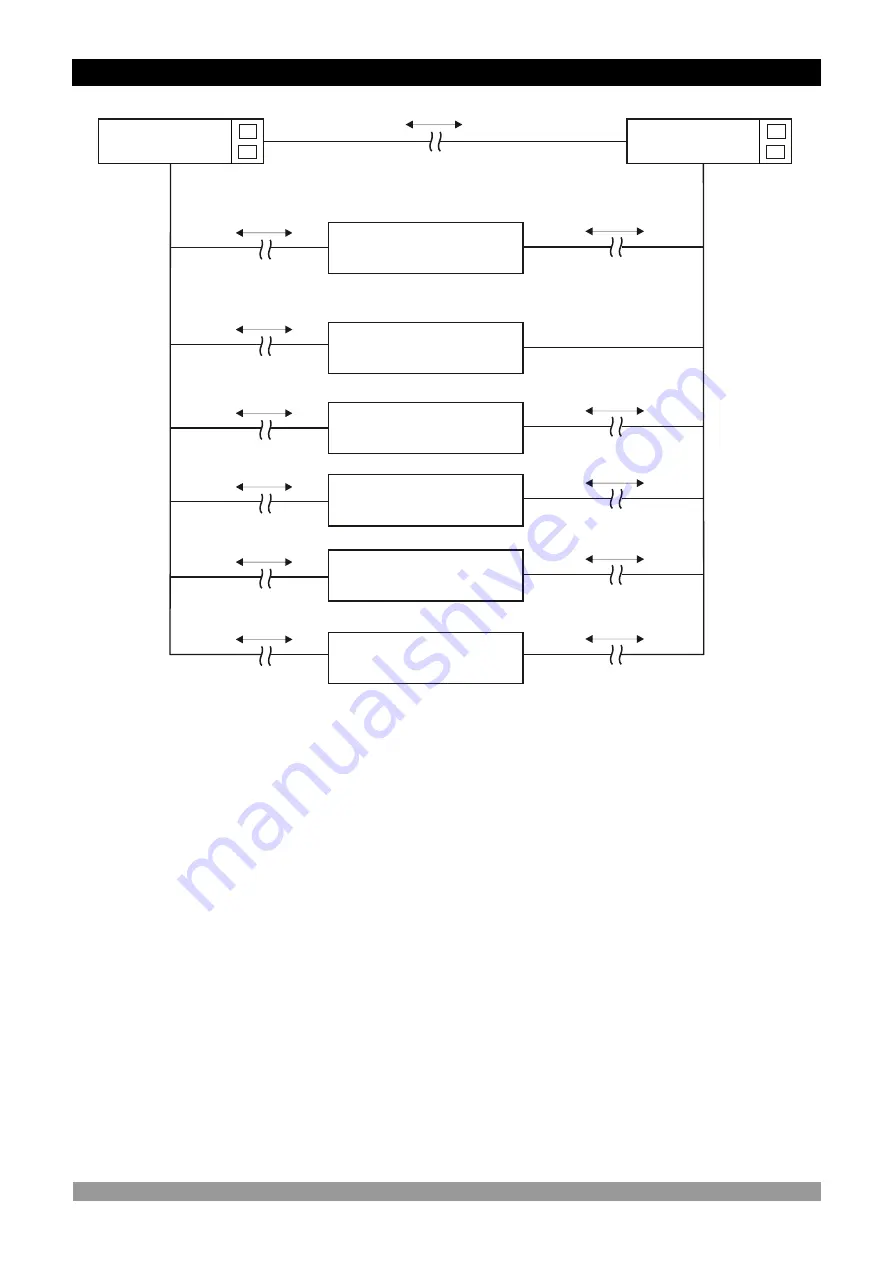
  3.6 Galvanic Isolation Test Values of EPLC9600-CHANNEL8 with Transistor Outputs

Analog inputs

500V


V

500V


V

Supply Input

of Output Card

2000V


V

500V


V

500V


V

14

15

29

30

18 

2000V


V

2000V


V

2000V


V

2000V


V

Summary of Contents for EPLC9600-CHANNEL8

Page 1: ...Relay or pnp source transistor output Sensor error detection Adjustable temperature offset 3 Different alarm and pre alarm types for each channel High Low and Band Alarms User defined channel labels D...

Page 2: ...ined Operation Also in these sections there are warnings to prevent serious injury while doing the physical and electrical mounting or using the device Explanation of the symbols which are used in the...

Page 3: ...TOR OUTPUTS 4 CABLE CONNECTION BETWEEN RS232 TERMINAL OF THE DEVICE AND PC 5 CONNECTION FOR RS485 SERIAL COMMUNICATION 6 DEFINETION OF THE FRONT PANEL AND ACCESSING TO THE PARAMETERS 6 1 DEFINETION OF...

Page 4: ...EC The Low Voltage Directive 2004 108 EC The Electromagnetic Compatibility Directive has been designed and manufactured to the following specifications EN 61000 6 4 2007 EMC Generic Emission Standard...

Page 5: ...ive Machine production industries etc Applications Heating Baking Ovens Incubators Storages Air Conditioning etc 1 Preface 1 1 General Specifications RS232 Communication Standard RS485 Modbus RTU Prot...

Page 6: ...pairs should only be performed by trained and specialized personnel Cut power to the device before accessing internal parts Do not clean the case with hydrocarbon based solvents Petrol Trichlorethylen...

Page 7: ...eep the power off until all of the wiring is completed so that electric shock and trouble with the unit can be prevented Never attempt to disassemble modify or repair this unit Tampering with the unit...

Page 8: ...urface maximum thickness 15 mm 0 59 inch Mounting Clamp 2 1 General Description 2 2 EPLC9600 CHANNEL8 Front View and Dimensions of 96 mm 3 78 inch 96 mm 3 78 inch 12 1 mm 0 47 inch 84 mm 3 31 inch Max...

Page 9: ...2 3 Panel Cut out 9 129 mm 5 08 inch min 92mm 3 62 inch 92mm 3 62 inch 129 mm 5 08 inch min...

Page 10: ...2 4 Environmental Ratings Operating Temperature 0 to 50 C Max Operating Humidity 90 Rh non condensing Altitude Up to 2000m Operating Conditions Forbidden Conditions Corrosive atmosphere Explosive atm...

Page 11: ...vice will not fall while doing the montage 2 6 Installation Fixing Clamp The unit is designed for panel mounting 1 Insert the unit in the panel cut out from the front side 2 Insert the mounting clamps...

Page 12: ...t the unit against damage and to prevent failure Keep the power off until all of the wiring is completed so that electric shock and trouble with the unit can be prevented 3 Electrical Wirings 3 1 Term...

Page 13: ...T CH 2 ALARM OUTPUT CH 3 ALARM OUTPUT CH 4 ALARM OUTPUT CH 5 ALARM OUTPUT CH 6 ALARM OUTPUT CH 7 ALARM OUTPUT CH 8 ALARM OUTPUT GENERAL ALR OUTPUT GENERAL PRE ALR OUTPUT 5 x 5A 250VV USB 2 0 COMMUNICA...

Page 14: ...3 ALARM OUTPUT CH 4 ALARM OUTPUT CH 5 ALARM OUTPUT CH 6 ALARM OUTPUT CH 7 ALARM OUTPUT CH 8 ALARM OUTPUT GENERAL ALR OUTPUT GENERAL PRE ALR OUTPUT USB 2 0 COMMUNICATION ETHERNET OR RS485 COMMUNICATION...

Page 15: ...ower supply switch and a fuse must be added to the supply voltage input Power supply switch and fuse must be put to a place where user can reach easily Power supply switch must be two poled for sepera...

Page 16: ...supply voltage There is no power supply switch on the device So a power supply switch must be added to the supply voltage input In accordance with the safety regulations the power supply switch shall...

Page 17: ...V Relay Outputs RS 232 RS 485 Usb 2000V V Ethernet 3 5 Galvanic Isolation Test Values of EPLC9600 CHANNEL8 with Relay Outputs Analog inputs 17 Supply Input of Device 14 15 2000V V 2000V V 2000V V 200...

Page 18: ...RS 232 RS 485 Usb 2000V V 1500V V Ethernet 3 6 Galvanic Isolation Test Values of EPLC9600 CHANNEL8 with Transistor Outputs Analog inputs 500V V 500V V Supply Input of Output Card 2000V V 500V V 500V...

Page 19: ...er 9 Pin DCON connection Cable Lenght must be max 12 meters for 9600 baud rate 1 2 3 4 5 6 7 8 9 10 11 12 13 14 15 16 17 18 19 20 21 22 23 24 25 26 27 28 29 30 TX NA RX GND NA NA 19 4 Cable Connection...

Page 20: ...d Cable lenght can be maximum 1000 meters in 9600 baud rate When baud rate increases cable lenght must be decreased 1 2 3 4 5 6 7 8 9 10 11 12 13 14 15 16 17 18 19 20 21 22 23 24 25 26 27 28 29 30 D D...

Page 21: ...tering the symbol character for string type variables in variable value changing screen DOWN BUTTON This button is used to decrement the digit which cursor is show of variable in variable value changi...

Page 22: ...right button for accessing the main operation screen 2 If the display scan parameter value DSP SCAN 1 each main operation screen is showing on LCD screen during time defined by SCANTIME parameter val...

Page 23: ...y SCANTIME parameter value i If more than one alarm messages is present each alarm message is showing on LCD screen during 1 second i 23 MAIN OPERATION CHANNEL 4 SCREEN MAIN OPERATION CHANNEL 1 SCREEN...

Page 24: ...button for accessing to password entering screen Enter the operator parameter section password with cursor lef right up and down buttons OPERATOR PARAMETER SCREEN CHANNEL 1 PARAMETERS Press enter butt...

Page 25: ...ameter screen Other operator section parameters can be accessed with same method explained above press escape button for return to main operation screen 25 Minimum Maximum 200 0 650 0 100 0 Change the...

Page 26: ...chnician parameter section password with cursor lef right up and down buttons TECHNICIAN PARAMETER SCREEN PAGE 1 CHANNEL 1 PARAMETERS Press enter button for accessing to the technician section paramet...

Page 27: ...ng next parameter page press up button for accessing previous parameter page TECHNICIAN PARAMETER SCREEN PAGE 6 RS 485 PAGE TECHNICIAN PARAMETER SCREEN PAGE 7 USB PAGE Press down button for accessing...

Page 28: ...o main operation screen Press down button for accessing next parameter page press up button for accessing previous parameter page If the device has a optional ETHERNET communication then ETHERNET page...

Page 29: ...left side of the display and can be selected by pressing the channel selection buttons i Min Max Default Unit ALARM SET Alarm Set Value For Channel X O C 650 0 200 0 100 0 PRE A SET Pre Alarm Set Valu...

Page 30: ...m disable 1 Sensor break alarm enable 6 6 1 Page 1 Parameters Technician Parameter Page Number Min Max Default Unit ALARM TYPE Alarm Type For Channel X 3 1 2 PRE A TYPE Pre Alarm Type For Channel X 3...

Page 31: ...2053 CH 2 BAND ALARM 42057 CH 3 BAND ALARM 42061 CH 4 BAND ALARM 42065 CH 5 BAND ALARM 42069 CH 6 BAND ALARM 42073 CH 7 BAND ALARM 42177 CH 8 BAND ALARM 42181 Parameter Name CH 1 SENSOR ALARM Modbus A...

Page 32: ...play channel scanner mode OFF Display channel scanner mode ON SCAN TIME Display scan period is adjusted by this parameter All main operation screen is displayed during time defined by this parameter L...

Page 33: ...1 1 0 1 ENA DIS CH 5 I O Channel 5 Enable Disable 42112 1 0 1 ENA DIS CH 6 I O Channel 6 Enable Disable 42113 1 0 1 ENA DIS CH 7 I O Channel 7 Enable Disable 42114 1 0 1 ENA DIS CH 8 I O Channel 8 Ena...

Page 34: ...r RS232 is can be adjusted by this parameter If parameter value ID Modbus communication device ID for RS232 is can be adjusted by this parameter This parameter value is can be adjusted from 1 to 247 e...

Page 35: ...sted by this parameter If parameter value ID Modbus communication device ID for RS485 is can be adjusted by this parameter If the device has a optional RS485 communication then RS 485 page is observed...

Page 36: ...130 6 129 1 130 5 129 5 130 0 129 9 130 3 129 1 SAMPLE 2011 06 23 17 26 09 130 6 129 1 130 5 129 5 130 0 129 9 130 3 129 1 SAMPLE 2011 06 23 17 26 10 130 6 129 1 130 5 129 5 130 0 129 9 130 3 129 1 SA...

Page 37: ...be adjusted by this parameter If DHCP is selected as a enable there is no need to adjust to this parameter if DHCP is selected as a disable then user must adjust this parameter 37 PORT SET Ethernet p...

Page 38: ...meter 38 SECOND Second value for RTC time is adjusted by this parameter Press and hold on 3 seconds Enter button for setting the RTC time value Min Max Default Unit YEAR Year Value For RTC Time 3000 2...

Page 39: ...ue Alarm Output SET HYS SET HYS ON OFF Alarm Output Process Value BandAlarm SET SET BAND 2 SET BAND 2 HYS HYS SET Alarm or Pre Alarm Set value HYS Hysteresis value forAlarm and Pre Alarm output BAND B...

Page 40: ...alue Address 30001 O C CH 2 P VALUE Channel 2 Process Value 30002 O C CH 3 P VALUE Channel 3 Process Value 30003 O C CH 4 P VALUE Channel 4 Process Value 30004 O C CH 5 P VALUE Channel 5 Process Value...

Page 41: ...Break Protection Upscale Sampling Time 400msecs Input Ressistance 10MW Digital Output Transistor or relay outputs Transistor Output PNP source type transistor output M Relay Output Resistive Load 5A 2...

Reviews: