


1592019030 XEV02D GB r1.2 04.06.2015
XEV02D
2/4
Alarm reset is automatic and happens as soon as control exceeds value set in parameter
dSL
.
If
oA1=CPr
, the regulation always re-starts after expiring both anti-short cycle timers
2on
(minimum
time between two consecutive compressor activations) and
2oF
(minimum time between one
compressor stop and next start-up).
Press any key to deactivate the buzzer at any time.
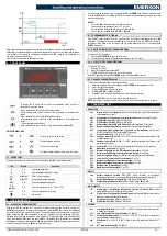
5. FRONT PANEL
To display and to modify the set point. In programming mode it selects a
parameter or it confirms a value
Keep it pressed for 3 sec to enter the information menu
In programming mode it slides the codes of the parameters or it increases their
values
Keep it pressed for 3 sec to enter the information menu
In programming mode it slides the codes of parameters or it decreases their
values.
To enter the alarms archive menu
Keep it pressed for 3 sec to switch OFF and ON the device (if
A2F=oFF
)
KEYS COMBINATIONS
+
To lock or to unlock the keyboard
+
To enter programming mode
+
To exit from various menu
+
To erase the alarm database (when into alarm menu)
5.1
XEV01D LEDS
On display there are some luminous dots. Their meaning is described in the following table:
LED
MODE
Function
L
ON
Low temperature alarm
H
ON
High temperature alarm (DLT alarm)
BLINKING
TRIAC output is working
RS
BLINKING
Serial communication is working
kPA
ON
Units of measurement in dakPA
°C, °F,
bar, PSI
ON
Units of measurement in °C, °F, bar or PSI
sec
ON
Units of measurement in seconds
ON
Alarm active
6. USER INTERFACE
6.1
ACCESS THE VARIABLES MENU
Keeping the
UP
key pressed for 3 sec when in normal operation mode (variables display) with
U2F=viS
, grants access to variables’ quick display menu. Press the
SET
key to switch from displaying
the variable’s label to its value, and vice-versa. The variables displayed in sequence are: cycle time of
digital modulating (
tdG
label) expressed in seconds, regulation input in percentage (
irP
label),
regulation input expressed as analogical value (
iAn
label), P2 probe input (
P2
label), valve regulation
output in percentage (
PEr
label), the used machine configuration (
CtY
parameter), the parameter
indicating any change on critical parameters (
Mod
). In addition to these, the firmware release date can
be read by using par.
FYr
(year),
FMn
(month) and
FdY
(day).
Scroll the variables inside the menu by pressing the
UP
and
DOWN
keys. Whatever position you are
in, press the
SET+UP
keys or waiting for the 60 sec time-out to expire without pressing any key to exit
the quick display menu.
NOTES:
-
Cycle time
tdG
is indicated in seconds with “sec” LED on
-
Values display in percentage go from 0.0% to 100.0%
-
The temperature is displayed with its units of measurement
-
This procedure is possible when
t1F
,
U2F
or
d2F=viS
6.2
PROGRAMMING CYCLE TIME tdG
Keep the
SET
button pressed for 3 sec to gains access to the digital modulating menu time (
tdG
parameter). The display will show the
tdG
label once accessed. Press the
SET
key to switch to
parameter’s value. Menu exit is for time-out (60 sec without pressing any key) or by pressing the
SET+UP
keys again.
6.3
HOW TO: ENTERING “PR1” PARAMETER MENU
To access the “Pr1” level menu:
1.
Keep both
SET+DOWN
buttons pressed for 3 sec.
2.
The instruments will show the first parameter present in the “Pr1” menu.
6.4
ACCESS TO “PR2” PARAMETER MENU
To access to “Pr2” menu:
1.
Enter the “Pr1” menu
2.
Select “Pr2” parameter and press
SET
.
3.
The “
PAS
” label will be shown, then “
0—
” with 0 blinking.
Insert “
321
” password through
UP
and
DOWN
buttons,
then press
SET
to confirm.
6.5
CHANGE A PARAMETERS VALUE
To change any parameter value, follow this procedure:
1.
Enter the Programming mode by keeping the
SET+DOWN
buttons pressed for 3 sec.
2.
Select the required parameter.
3.
Press the
SET
button to display the value.
4.
Use
UP
or
DOWN
to change the value.
5.
Press
SET
to store the new value and move to the following parameter.
To exit: press
SET+UP
or wait for 30 sec without pressing any button.
NOTE
: the set value is stored even when the procedure is exited by waiting the time-out to expire.
7. PARAMETER LIST
REGULATION
oA1
Digital output 1 configuration:
nu
=not used;
ALr
=alarm output;
CPr
=compressor
output;
dmd
=do not use it.
oA2
Digital output 2 configuration (open collector output):
nu
=not used;
ALr
=alarm.
oP1
Digital output 1 polarity: oP
=open
; CL
=closed.
oP2
Digital output 2 polarity: oP
=open
; CL
=closed.
tbA
Alarm output deactivation (only if oAx=ALr): n
=not permitted;
Y
=permitted
.
bEn
Buzzer (software) management: on
=buzzer active;
oFF
=buzzer disabled.
P2C
Temperature probe configuration (it depends on the hardware): nu
=not used;
Pt1
=PT1000;
ntC
=NTC10k probe;
n86=
NTC86k probe.
o2
Probe P2 calibration:
-12 to 12°C; -21 to 21°F
PA4
Analogue input at 4mA or 0V:
(0 to 100%) set the percentage value relative to the
minimum analog input.
P20
Analogue input at 20mA or 10V:
(0 to 100%) set the percentage value relative to the
maximum analog input.
Sut
Start up time:
(0.0 to 25.5 sec) valve activation time before starting the regulation.
tdG
Modulation time interval:
6 to 40 sec.
2on
Minimum delay between two DG compressor start-ups:
0 to 255 min
2oF
Delay between DG compressor switch-off and start-up:
0 to 999 sec
odo
Power on regulation delay:
(0 to 999 sec) the regulation starts after this delay
dSL
Lower limit for control signal (in percentage):
0 to 100%
Si0
Minimum analogue input value (in percentage):
0 to 100%
Si1
Maximum analogue input value (in percentage):
0 to 100%
PMi
Minimum load (in percentage):
0 to 100%
PMA
Maximum load (in percentage):
0 to 100%
DISPLAY
Lod
Default displayed variable: PEr
=TRIAC output activation in percentage;
Ain
=analogue input value in percentage;
P2
=temperature measured form probe P2.
CF
Units of measurement for temperature: °C
=Celsius;
°F
=Fahrenheit.
rES
Temperature resolution (valid only if CF=°C): in
=integer;
dE
=decimal.
DIGITAL INPUTS
i1F
Digital input 1 configuration (voltage free contact): nP
=disabled;
EAL
=external
alarm;
bAL
=block alarm;
onF
=regulation enabled.
i2F
Digital input 2 configuration (powered input): nP
=disabled;
EAL
=external alarm;
bAL
=block alarm;
onF
=regulation enabled.
i1P
Digital input 1 polarity: oP
=open
; CL
=closed.
i2P
Digital input 2 polarity: oP
=open
; CL
=closed.
ALARMS
ALL
Low temperature alarm:
(-30 to 200°C; -22 to 392°F) this alarm blocks the regulation.
A manual reset required.
dLL
Low temperature alarm activation delay:
0 to 999 sec
dLt
Discharge line temperature:
(-30 to 200°C; -22 to 392°F) value used for compressor
block and alarm output activation.
dth
Differential:
(0 to 99.9°C; 0 to 999°F) used to restart the compressor after any DLT
alarm.
dLd
DLT alarm activation delay:
0 to 999 sec


