background image

Emerson Process Management GmbH & Co. OHG

 1-13

1

Techn. Description

X-STREAM X2FD

Instruction Manual

HASXMDE-IM-EX
01/2015

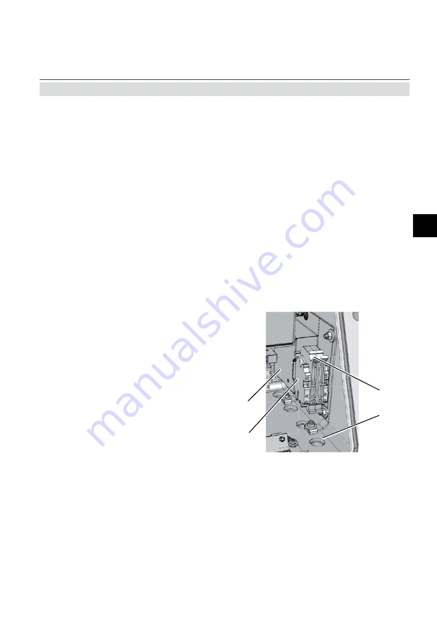
Fig. 1-6:  Power terminals / fuse holders

1.7  Technical Data

Power Connection

Connection via internal screw terminals near
cable entries, (

fi

 g. 1-6).

Cross section: 

max. 4 mm

 (10 AWG), end sleeves not 

 required 
Cable entry via  

1 cable gland, classi

fi

 ed IP 68 or suitable 


conduit with metric-to-NPT adaptor

Permissible outer cable diameter for power  
cord: 

see cable gland / conduit speci

fi

 cation

Power supply fuses

The power terminals integrate fuse holders.
Fuse ratings: 

AC 230 V / T 4 A / 5x20 mm


Power terminals with integrated 

   fuse 

holders


Protective earth terminal (PE)


Power cable entry


EMI power supply 

fi

 lter

3

2

4

1

Summary of Contents for Rosemount Analytical X-STREAM X2 Series

Page 1: ...www EmersonProcess com Instruction Manual HASXMDE IM EX 01 2015 Gas Analyzer X STREAM X2 Series Flameproof Variation For Use in Zone 1 and Division 2 Hazardous Areas Instruction Manual Addendum ...

Page 2: ...peration and maintenance of the product Install your equipment as specified in the Installation Instructions of the appropriate Instruction Manual and per applicable local and national codes Connect all products to the proper electrical and pressure sources To ensure proper performance use qualified personnel to install operate update program and maintain the product When replacement parts are req...

Page 3: ...1 1 1 2 Design Features 1 1 1 3 Protective Measures in Detail 1 2 1 4 High Pressure Option Purge Option 1 3 1 5 Explosion Protection Compliances 1 4 1 5 1 Special Conditions for Safe Use 1 6 1 6 Nameplate Label Examples 1 7 1 7 Technical Data 1 8 1 8 Measurements Specifications 1 15 1 9 Vapor Recovery Application Simultaneous Measurement of CH4 and Non CH4 1 19 Chapter 2 Installation 2 1 2 1 Scope...

Page 4: ...ion alarms 3 29 3 9 6 Backing up the settings 3 35 Chapter 4 Service and Maintenance 4 1 4 1 Verifications and Tests 4 3 4 1 1 Routine Tests on Analyzer 4 3 4 1 2 Tests on Flame Arrestors 4 5 4 2 Replacement of Parts 4 7 4 3 Vapor Recovery Application Special Information 4 9 4 3 1 Determining the converter efficiency 4 10 4 3 2 Replacement Instructions 4 11 4 3 3 Failure Situation 4 15 4 4 Perform...

Page 5: ...el instrument for high gas pressure 2 11 Fig 2 9 Label with fastening torques installed at the instrument 2 11 Fig 2 10 Allocation of terminals 2 16 Fig 2 11 Terminals block X1 analog signals and relay outputs 1 4 2 18 Fig 2 12 Terminals block X1 Modbus interface 2 19 Fig 2 13 Modbus Interface Ethernet connector 2 20 Fig 2 14 Terminal blocks X4 1 and X4 2 Digital inputs and outputs 2 21 Fig 2 15 P...

Page 6: ...urement Performance Specifications 1 17 Tab 1 5 Special Performance Specifications for Gas Purity Measurements 1 18 Tab 3 1 Analog output signals settings and operational modes 3 22 Tab 3 2 Analog outputs Scaling examples 3 28 Tab 3 3 Influence of SpanRange parameter on concentration alarm limits 3 30 Fig 4 8 Converter filling sequence 4 13 Fig 4 9 Jacket in converter assembly 4 14 Fig 4 10 Heated...

Page 7: ...and therefore may describe configurations and or options not part of your specific analyzer PREAMBLE The following definitions apply to WARNINGS CAUTIONS and NOTES found throughout this publication DEFINITIONS HIGHLIGHTS AN OPERATION OR MAINTENANCE PROCEDURE PRACTICE CONDITION STATEMENT ETC If not strictly observed could result in injury death or long term health hazards of personnel NOTE Highligh...

Page 8: ...xygen to burn Flammable Gas es Gases and gas mixtures are assigned to be flammable if they might become ignitable when in a mixture with air Explosive Gas es Flammable Gases and gas mixtures in a mix ture with air within the explosive limits Intrinsically Safe Cell IS Cell Cells supplied with an intrinsically safe power signal approved by a Test Institute to operate with explosive gases The design...

Page 9: ...y be accessible Removing covers by qualified personnel is permitted only if the instrument is disconnected from power Nevertheless several surfaces may remain hot for a limited time more detailled information available see in struction manual before proceeding more detailled information available see in struction manual before proceeding Wherever one or more of the following symbols appear on or i...

Page 10: ...al means dangerous voltages may be exposed hot surfaces may be exposed possible danger of explosion toxic substances may be present substances harmful to health may be present indicates notes relating to heavy instruments electrical components may be destroyed by electrostatic discharges units must be disconnected from the power source indicates special instructions or information for operation at...

Page 11: ...meproof X STREAM X2FD gas analyzers in hazardous classified areas only For comprehensive information on operating and maintain service the instrument in a safe manner it is MANDATORY to read all additional instruction manuals if not provided as printed version see the accompanying USB stick for an electronic version PDF The following instruction manuals are available and or referenced within this ...

Page 12: ...this instruction manual and receiving appropriate training Special Conditions for Safe Use Only specified screws M16x45 ISO 4762 A2 70 as specified in the maintenance section of this manual shall be used spare part 42716945 The flame joints correspond to the drawing No 4 271 7112 1 and do not comply with the dimensions mentioned into the Tab 1 and Tab 2 of EN 60079 1 ed 2 The gas path for the samp...

Page 13: ...ce Any modifications to the device not meeting these requirements will void the product certification s Contact Emerson Process Management s customer service center for return authorization POSSIBLE EXPLOSION HAZARD Do not open instrument when energized Ensure that external circuitry is disconnected or de energized before opening the instrument Ensure that all gas connections are made as labeled a...

Page 14: ...llation and connecting mains and signal cables are subject to qualified personnel only taking into account all applicable standards and legislative requirements Failure to follow may cause warranty invalidation property damage and or personal injury or death Connecting mains and signal cables to internal srew terminals requires working at open housing near life parts Installation of this instrumen...

Page 15: ...anual relates intended to be wall mounted and or outdoor installed weighs up to approx 63 kg 139 lbs depending on included options Use two people and or suitable tools for transportation and lifting these instruments Take care to use anchors and bolts specified to be used for the weight of the units Take care the wall or stand the unit is intended to be installed at is solid and stable to hold the...

Page 16: ...Emerson Process Management GmbH Co OHG S 10 X STREAM X2FD Instruction Manual HASXMDE IM EX 01 2015 Safety Instructions ...

Page 17: ...Zone 1 or occa sionally Zone 2 Division 2 The basic concept used to protect the sur rounding atmosphere from being ignited if an internal failure results in high temperatures flames or even an explosion is to keep the explosion inside the enclosure and quench all flames possibly passing through the flange To provide adequate explosion protection the X STREAM X2FD analyzer features a cast aluminum ...

Page 18: ...4 outer diameter OD Optionally a clamping ring for 6 mm OD may be used replacing the 6 35 mm version Unused threads are closed with blind plugs which are certfied within the emerson approvals Cables are fed into the enclosure utilizing up to 4 cable glands located at the enclosure s bottom right side For installation in NorthAmerica cable glands are replaced by a combination of conduits and metric...

Page 19: ...o support both situations higher sample and calibration gas pres sures as well as purging the housing with a gas for best measuring results at low concentrations To permit this special additional conditions must be taken into account Higher sample and calibration gas pres sures Higher gas pressure is specified to be within the range of 1100 hPa to 1500 hPa The ma ximum permitted flow is 1 5 l min ...

Page 20: ...ns of CAN CSA E60079 0 02 R2006 CAN CSA E60079 1 02 R2006 ANSI ISA 12 00 01 2002 IEC 60079 0 Mod ANSI ISA 12 22 01 2002 IEC 60079 1 Mod Furthermore these X STREAM X2FD analy zers are certified for use in Class I Division 2 Group BCD T3 areas See appendix for a copy of the CSACertificate of Compliance IECEx certification enables worldwide appro vals with minimized need of testing Further more based...

Page 21: ...n case of gas pressure above 1100 hPa to 1500 hPa Appropriate certified cable glands shall be used in accordance with IEC EN 60079 14 Vapor Recovery application Pressure of gases not to exceed 1100 hPa Concentrations of gases must be below 25 LEL Depending on the particular application all approbriate safety instructions mentioned in this instruction manual on hand must be considered Take special ...

Page 22: ...en T4 Temperature Class 135 C Gb Equipment Protection Level Tamb Ambient Temperature Range IP66 Type 4X Enclosure Rating outdoor use AEx Explosion protected US Ex Explosion protected CAN d flameproof IIB H2 Group II Gas Group B plus Hydrogen T3 Temperature Class 200 C Tamb Ambient Temperature Range IP66 Type 4X Enclosure Rating outdoor use Additional Division Marking if applica ble Class I Flammab...

Page 23: ...tion Protection class IP 66 EN 60529 Type 4X for outdoor installation if appli cable see nameplate label Analyzer must not be exposed to direct sun light Gas fittings quantity max 8 specification flame arrestors with fittings connections 6 4 mm or 1 4 stainless steel Cable inlets enclosure threads M20 x 1 5 Flame arrestors with gas fittings enclosure threads M18 x 1 5 Eyebolt detail All dimensions...

Page 24: ...ot be operated in corrosive atmosphere Power supply Rated input voltage 100 240 V 50 60 Hz wide range input Power supply voltage fluctuations are not to exceed 10 of the nominal supply voltage Input voltage range 85 264 V 47 63 Hz Nominal input current standard 1 3 0 7 A max with temperature control 3 1 5 A max General Purpose Compliances Electrical safety CAN USA CSA C US based on CAN CSA C22 2 N...

Page 25: ...gurable via keypad and Modbus 4 relay outputs dry contacts max load 30 V 1 A 30 W resistive Each output can be configured to one of the following functions NAMUR NE 107 status signal Failure Maintenance request Out of specification Function check 1 of 2 concentration limits per channel Control signals for external valve V1 V8 external sample gas valve external pump Zoom status for analog outputs O...

Page 26: ...alibrate all channels Abort calibration Zoom analog output 1 Zoom analog output 2 Zoom analog output 3 Zoom analog output 4 9 or 18 additional relay outputs dry contacts max load 30 V 1 A 30 W resistive Each output can be configured to one of the following functions NAMUR NE 107 status signal Failure Maintenance request Out of specification Function check 1 of 2 concentration limits per channel Co...

Page 27: ...pen to the ambience of the analyzer if the measured gas concentration is below 25 V V LEL Otherwise it must end in a safe area Purging the housing with clean gas when e g measuring low concentrations Maximum gas flow 2 l min Permitted purge medium Inert gas or air Dry clean free of corrosives or components containing solvents and free of components to be measured Its temperature must correspond to...

Page 28: ... cross section max 1 5 mm2 14 AWG end sleeves not required Cable entry via three IP 68 cable glands or conduits Permissible cable outer diameter see cable gland conduit specification Available signals standard Analog signal outputs Relay status signals Modbus interface RS232 RS 485 optional Digital inputs outputs Modbus RJ45 ethernet connector Detailed terminals configuration Chapter 2 Installatio...

Page 29: ...oss section max 4 mm2 10 AWG end sleeves not required Cable entry via 1 cable gland classified IP 68 or suitable conduit with metric to NPT adaptor Permissible outer cable diameter for power cord see cable gland conduit specification Power supply fuses The power terminals integrate fuse holders Fuse ratings AC 230 V T 4 A 5x20 mm 1 Power terminals with integrated fuse holders 2 Protective earth te...

Page 30: ...2 H2 IR 0 3 0 100 Ammonia NH3 IR 0 100 ppm 0 100 Argon Ar TCD 0 50 0 100 Carbon dioxide CO2 IR 0 5 ppm 5 0 50 ppm 0 100 Carbon monoxide CO IR 0 10 ppm 5 0 50 ppm 0 100 Chlorine Cl2 UV 0 300 ppm 0 100 Ethane C2 H6 IR 0 1000 ppm 0 100 Ethanol 1 C2 H5 OH IR 0 1000 ppm 0 10 Ethylene C2 H4 IR 0 400 ppm 0 100 Helium He TCD 0 10 0 100 Hexane 1 C6 H14 IR 0 100 ppm 0 10 Hydrogen 4 H2 TCD 0 1 0 100 Hydrogen...

Page 31: ...ated photometer bench 6 Depending on measuring range 7 Pressure sensor is required 8 Special conditions for 1100 hPa abs 1 5 psig 9 Limited to atmospheric if internal sample pump 10 Temperatures below 0 C 4 F with thermostat control only 11 Thermost controlled sensor 75 C 167 F 12 Flow variation within 0 1 l min 13 Optional thermostatically controlled box with temperature 60 C 140 F 14 Temperature...

Page 32: ... hPa abs 7 psig Influence of pressure 2 At constant temperature 0 10 per hPa 0 10 per hPa 0 10 per hPa With pressure compensation 6 0 01 per hPa 0 01 per hPa 0 01 per hPa Permissible ambient temperature 9 0 20 to 50 C 32 4 to 122 F 5 to 45 C 41 to 113 F 5 to 45 C 41 to 113 F Influence of temperature 1 13 at constant pressure On zero point 1 per 10 K 1 per 10 K 1 per 10 K 5 On span sensitivity 1 pe...

Page 33: ...l conditions for 1100 hPa abs 1 5 psig 0 10 50 ppm CO 0 5 50 ppm CO2 Detection limit 4 σ 1 2 2 Linearity 1 2 1 Zero point drift 1 2 3 2 resp 0 2 ppm 9 Span sensitivity drift 1 2 4 2 resp 0 2 ppm 9 Repeatability 1 2 2 resp 0 2 ppm 9 Response time t90 7 10 s Permissible gas flow 0 2 1 5 l min Influence of gas flow 1 2 2 Maximum gas pressure 10 1500 hPa abs 7 psig Influence of pressure 5 At constant ...

Page 34: ...bons mainly CH4 in the sample gas After switching power on wait about 50 min for the converter to reach its operating tempera ture before applying gases FA1 Analyzer s inlet flame arrestor FA2 3 Analyzer s outlet flame arrestors F1 Filter T1 Throttle V1 Valve The configuration consists of a dual channel IR measurement connected to the inlet and outlet of a converter This converter is instal led in...

Page 35: ... highly depen dent on the converter efficiency If this is too low the converter material needs replace ment To measure the converter efficiency one has to compare the measurement values of CH1 with and without having the gas flowing through the converter This requires activating the valve V1 4 Maintenance section of this manual for instructions about when and how to replace the converter material ...

Page 36: ...We recommend to keep the packaging available for future transportation because only the ori ginal packaging ensures proper protection 2 1 Scope of Supply USB stick Analyzer Instruction manuals This manual addendum X STREAM X2 instruction manual on USB stick Allen key for flange screws Metric 2 NPT adaptors for CSA approved analyzers amount meets number of non sealed threads Fig 2 1 Scope of Supply...

Page 37: ...th no hazardous atmos phere is present and the instrument and connected external circuitry are de energized Depending on the local regulation this may require a competent hot work supervisor to issue a hot work permit HEAVY INSTRUMENT The analyzer model X STREAM X2FD to which this manual relates intended to be wall mounted and or outdoor installed weighs up to approx 63 kg 139 lbs depending on inc...

Page 38: ...XPLOSION HAZARD Failure to follow this instruction and operating the analyzer without properly threaded components may result in explosion hazards EXPLOSION HAZARD Consider the permitted fastening torques when installing components to the enclosure or closing the cover as given in this section and on a label at the instrument 2 6 ...

Page 39: ...tions may affect the measuring results 2 2 Installation Analyzer Fig 2 2 Dimensions IMPORTANT NOTE When installing the analyzer take care to have an area of min 40 mm surrounding the flange free of any solid components not part of the instrument to ensure proper function of the flange Cable inlets enclosure threads M20 x 1 5 Flame arrestors with gas fittings enclosure threads M18 x 1 5 Eyebolt det...

Page 40: ...gas lines e g by corrosi on or solvents Pressure and gas flow must remain within the values given in the Measurement Specifications section within this manual If moisture cannot be avoided it is necessary to ensure that the dew point of the gases is at least 10 C 18 F below the ambient tempe rature to avoid condensate in the gas lines Hints for selected gases Calibration gases for CO and NO need t...

Page 41: ...ure if gases are supplied which may harm analyzer components if due to a leak released into the analyzer enclosure Open reference option In some cases the measuring cell has an open reference side to be supplied with nitrogen This nitrogen at least should be of quality 5 0 which means nitrogen of purity 99 999 If such gas is not available the substitute must be dry clean and free of corrosi ves or...

Page 42: ...epared beforehand When supplying aggressive gases ensure that the gas lines are not damaged Max admissable pressure 150 kPa 7 psig atmospheric with internal pump Exhaust lines must be installed to incline downwards and be unpressurized and protected against frost and conform to legal requirements TRACE OXYGEN MEASUREMENTS The sensor for trace oxygen measurements is a consumable Remaining lifetime ...

Page 43: ...h PVC caps to prevent pollution by moisture dust etc Fig 2 3 Labelling of gas connectors example Pressure control valve Flow sensor Exhaust Exhaust Analyzer Sample gas pump Filter Fig 2 4 Installation in bypass mode The analyzer should be mounted close to the sample gas source to minimize transportati on time A sample gas pump can be used to reduce the reaction time this requires that the analyzer...

Page 44: ...hreat 7 O ring shoulder FA 01 with 1 4 outside instrument and 1 8 inside FA 02 with 1 4 at both ends FA 03 with 1 8 at both ends Fig 2 6 Flame arrestor elements exemplarly considering FA 01 When thightening the fitting counterhold the flame arrestor with a wrench placed at the hexagon items 5 of fig 2 3 next to the cap nut items 1 4 to be tightened Always counterhold the flame arrestor while thigh...

Page 45: ...estor purge gas inlet installed into the analyzer enclosure Another flame arrestor must be installed operating as a breathing device purge gas outlet Connection of breathing device The external output of the breathing device exhaust can be open to the ambience of the analyzer if inert gas is used as purge medium If air is used the output must end in a safe area if the measured gas concentration is...

Page 46: ...as to be installed operating as a breathing device limiting the internal pressure rise in case of gas path leakage Connection of breathing device Theexternaloutputofthebreathingdevice ex haust may beopentotheambienceoftheana lyzer ifthemeasuredgasconcentrationisbelow 25 V V LEL Otherwise it must end in a safe area 2 4 1 2 High Sample and Calibration Gas Pressures 2 4 1 3 Fastening Torques for Encl...

Page 47: ...witch A power switch or circuit breaker complying with IEC 60947 1 3 has to be provided in the building installation This switch has to be installed near by analyzer must be easily operator accessible and has to be assigned as disconnector for the analyzer Disconnect instruments with screw terminals from power when working at power terminals pull power plug or operate power switch circuit breaker ...

Page 48: ...stay compliant with the North American certification use only flameproof certified adaptors e g the following type Redapt AD U series stainless steel with captive o ring seals size male M20 x 1 5 to female 3 4 NPT or 1 2 NPT Select a type of conduit according the local code suitable for above mentioned adaptors and the site of installation During installation follow the instructions provided by th...

Page 49: ...for an original version of the cable gland or adapter installation instruc tions whatever is applicable INSTALLATION USING CABLE GLANDS X STREAM Flameproof analyzers are shipped without certified cable glands Cable glands have to be selected while preparing the installation according all applicable standards e g EN 60079 14 or IEC 60079 14 Use only cables as specified in the cable glands installat...

Page 50: ...Emerson Process Management GmbH Co OHG 2 15 2 Installation X STREAM X2FD Instruction Manual HASXMDE IM EX 01 2015 2 5 Installation Electrical Type AD U adapter installation instructions ...

Page 51: ...to provide suitable cable glands according all ap plicable standards e g IEC EN 60079 14 See maintenance section of this manual for recommended cable glands 1 4 2 3 5 Installation under CSA certification requires the use of approved conduits and suitable metric to NPT adaptors Both plugs and cable entries must be installed properly and fixed by applying the prescribed torque The instrument provide...

Page 52: ...e to be connected via screw terminals except the optional ethernet connector located inside the analyzer Preparation of signal cables Supported wire cross sections 0 14 to 1 5 mm2 26 to 15 AWG no need to use wire end sleeves Cable skinning length 5 mm 0 2 inch Screw thread M 2 Tightening torque min 0 25 Nm 2 3 in lb Installation with cable glands Ensure all required parts are available Cable gland...

Page 53: ...P4 9 P4 10 P4 11 P4 12 Relay Outputs Analog Outputs Serial Interface Configuration of relay output termi nals as per standard factory setting NAMUR status signals Fig 2 11 Terminals block X1 analog signals and relay outputs 1 4 Analog Outputs Relay Outputs 1 4 Terminals for analog signals and relais outputs 1 4 are located at the leftmost terminal module terminal block X1 fig 2 5 Analog outputs sp...

Page 54: ...rface signals Fig 2 12 Terminals block X1 Modbus interface Note Take care of the special installati on instructions in section 4 5 of the X STREAM gas analyzer series in struction manual Note 2 X STREAM analyzers are to be con sidered a DTE Data Terminal Equip ment Termi nal MOD 485 2 wire MOD 485 4 wire RS 232 P4 4 Common Common Common P4 5 not used not used RXD P4 6 not used not used TXD P4 7 no...

Page 55: ...oard in the card cage section of the unit fig 2 4 To install this connection a cable must be fed through the cable entry without a con nector The connector can be wired on when the free end has been fed into the instrument We recommend the VARIOSUB RJ45 QUICK ON connector PHOENIX CONTACT which is supplied with the unit and requires no spe cial tools Wiring instructions can be found in the separate...

Page 56: ...nal blocks X4 1 and X4 2 Digital inputs and outputs 2 5 Installation Electrical Note Take care of the special installation instruc tions in section 4 5 of the X STREAM gas analyzer series manual Digital inputs Quantity 9 1 terminal block or 18 2 terminal blocks dry change over relay contacts can be used as NO or NC Electrical specification max 30 VDC 1 A 30 W Quantity 7 1 terminal block or 14 2 te...

Page 57: ...ther conduits or cable glands given on page 2 11 Insert the power cord through the foremost entry strip the outer insulation skin and connect the conductors to the terminals a descriptive label is attached nearby the termi nals by inserting them from the bottom sides The power cord is connected to screw type terminals located inside the housing Electrical Connections Power terminals Screw terminal...

Page 58: ...l conductor located at the base part flange s rear side see fig 2 14 near the nameplate label Screw thread M5 x 10 mm Conductor cross section min 4 mm The installation has to comply with sound engineering practice see example to the right Take care of contact corrosion due to the aluminum cast enclosure Fig 2 16 Equipotential bonding conductor terminal 2 5 Installation Electrical 1 2 3 4 5 1 Lock ...

Page 59: ...ver by means of ALL 20 screws 2 5 Installation Electrical EXPLOSION HAZARD Do NOT operate the instrument with doors sealing plugs or covers open This is permitted only when no hazardous atmosphere is present Depending on the local regulation this may require a competent hot work supervisor to issue a hot work permit Use ALL 20 screws to fix the cover Violation may cause an explosion ELECTRICAL SHO...

Page 60: ...0 The sheet also gives instructions for the sequence of supply ing gases during process and analyzer startup OPERATION AT LOW TEMPERATURES When operating an instrument at temperatures below 0 C 32 F do NOT apply gas nor operate the internal pump before the warmup time has elapsed Violation may result in condensation inside the gas paths or damaged pump diaphragm Consider the related instructions i...

Page 61: ...ent e g cooler dust filters etc into a leak test 3 2 Performing a Leak Test Required tools U turn manometer for max 1 45 psi 100 mbar Stop valve Procedure Connect the water filled u turn manome ter to the analyzer s sample gas output disconnect external gas lines Install the stop valve between gas input fitting and a Nitrogen N2 supply Open the stop valve until the internal gas path is under press...

Page 62: ...g the unit For the first startup after installation follow the step by step in structions for navigating the menus allowing you to familiarise yourself with the unit and its software and if necessary adjust the settings to your needs EXPLOSION HAZARD Before applying power and signals Verify for proper installation Verify that all covers and plugs are properly installed and in place Verify that all...

Page 63: ...ration Apply gas Display Note Menus or lines on a grey background are optional or context dependent and are not always displayed Access levels Access level 1 user Access level 2 expert Access level 3 administrator Access level 4 service level Apply gas Convention Meaning Within descriptions Menu title 6 2 2 page 6 12 For a detailed description of this Menü see section 6 2 2 on page 6 12 CONTROL ZO...

Page 64: ...us information and the easy to use menu based user interface for entering parameters For ease of understanding the user can at any time select one of three languages stored in the unit currently available English French German Italian and Spanish in various com binations Fig 3 2 Front Panel 3 5 The user interface Units are operated using six keys on the front panel Three LEDs on the front panel en...

Page 65: ... displayed menu 3 5 2 Status LED 3 5 The user interface Three status LED indicate the unit s status recognisable from a distance Status is indicated in accordance with the German NAMUR NE 44 recommendations Failure is indicated when this red LED is lit A flashing red LED in the middle indicates Maintenance request Function check or Off spec operation The third green LED indicates the power supply ...

Page 66: ...ER key Mode Function Measuring Leaves the measurement dis play Browsing Accesses submenu or exe cutes command Editing Confirms new entry MEASURE key Mode Function Measuring no function Browsing Returns to measurement dis play Editing Cancels entry UP DOWN keys Mode Function Measuring Leaves the measurement dis play Browsing Selects menu line Goes to previous next page when currently in a line begi...

Page 67: ...ng Goes up 1 level or page in menu system Editing Moves cursor 1 space Leaves channel selection Cancels editing of given pa rameter Goes to previous page when showing in first line RIGHT key Mode Function Measuring Leaves the measurement display Browsing Accesses submenu Editing Goes to next page when showing in fourth line Moves cursor 1 space 3 5 The user interface ...

Page 68: ...s moved down with the DOWN key and up with the UP key If the cursor is in the first line pressing the key will move it to the last line If the cursor is in the last line pressing the key will move it to the first line An action in the selected line is initiated by pressing the key i e opening a new menu starting a procedure or entering edit mode Function Description Displaying TEXT Simple text not...

Page 69: ...nd the new value displayed if not an error message is displayed key Cancel all settings and changes are reset to their former values Browsing Some menus have more than four entries and these cannot all be displayed at once In these menus an indicator in the last or first line indicates the direction the menu continues in To show the following page the cursor is placed in the line with the indicato...

Page 70: ... minor relevance In this chapter the descriptions of the indi vidual menus also indicate which level the menus are in These assignments cannot be changed Access codes for levels 1 to 3 can be defi ned activated and deactivated by the client The analyzer is delivered with the following settings Level Access code Status 1 00000001 Off 2 00000002 Off 3 00000003 Off It is recommended to set new access...

Page 71: ...edure e g calibration has been started 3 6 Software Access Code 1 Code 00000001 Back Press Entering access codes If an access code is required for a menu the following message is displayed Information on incorrect entry The value entered by the user is outside valid limits The display indicates what limits apply Pressing returns the display to the previous screen to allow a valid setting to be ent...

Page 72: ...han four channels are installed in the unit only the values of the available channels will be shown Line 4 is also used to display plain text status information errors maintenance requests function checks or off spec performance If such messages are active line 4 alternates between the messages and the parameter selected for line 4 Active messages are stored in an internal buffer If there is more ...

Page 73: ...he intended language is set Note The fourth press of the ENTER key in this sequence access the Language parameter line 3 8 Selecting the language following sequence of keypresses starting at the measurement display can be used to set the language If the system has been set up accordingly the code for access level 1 must be entered at this point to enable access to the following menu Note The facto...

Page 74: ... EN English FR French DE German IT Italian ES Spanish PT Portuguese Note If you are unfamiliar with the language set page 3 14 shows the sequence to be used to set a different language Language Language EN If the system has been set up accordingly the code for access level 1 must be entered at this point to enable access to the following menu Note The factory setting for this unit is no code requi...

Page 75: ... special know ledge Incorrect entries may result in incorrect results or impair the performance of the unit This initial access to this menu is intended to gain information on the configuration of the unit 3 9 1 Installed options All X STREAM gas analyzers can be fitted with a variety of optional components follow these steps to see which options are installed on your analyzer Valves Internal COM ...

Page 76: ...4 Comp 4 Page 2 Select the value to be displayed in each line of the measurement display The following options are available Comp 1 Comp 4 Temp 1 Temp 4 Press 1 Press 4 Flow 1 Flow 4 Blank nothing Note X STREAM currently supports only one pres sure sensor Values Press 1 to Press 4 thus refer to the same sensor Setup Display Component Temperature Pressure Gasflow Page 3 The measurement units for th...

Page 77: ...st be correctly set for results to be accurate In multi channel units the values for each channel must be entered separately Calibration gases ZeroGas 0 0 ppm SpanGas 500 0 ppm 3 9 3 Calibration setup 3 9 Checking the settings Press the LEFT key to return to the CALI BRATION menu and check the entry for Tol Check The Tol Check tolerance check option is set to inactive Off by default When the toler...

Page 78: ...e between valves and measuring cell some time is required before the measuring cell is filled with the calibration gas this is the purge time which is to be entered here If the calibration is started earlier the gas lines will still contain other components and the calibration will be inaccurate Valve assignment This line is to assign internal and or external valves the function of either zero or ...

Page 79: ... the current air pressure here and adjust it when significant changes take place this improves the accuracy of the instrument Signal damping set in the DAMPING menu allows the smoothing of the measuring signal but also affects the reactio time of outputs and display The factory setting is 0 seconds and any value between 0 and 28 seconds can be set In multi channel units the value for each channel ...

Page 80: ...log outputs to be set according to the NAMUR NE43 recommendations The 0 20 mA operational mode generates a 20 mA signal when the concentration is measured at the upper limit of the signal range A 0 mA signal is generated when the sample gas concentration is at 0 dead zero However a severed cable would also result in a signal of 0 and so an external data capture system would not be able to recognis...

Page 81: ...ge as per Table 5 1 signal out of range signal slowly rises or falls towards the limits given in table 5 1 and holds that value until the concentration returns to within the measuring range failure signal out of range as per table 5 1 but not 0 severed cable no signal 0 mA Table 3 1 shows an overview of all available operational modes Tab 3 1 Analog output signals settings and operational modes Ou...

Page 82: ...he actual measured concentrati ons concentration alarms which may other wise be set off by the concentrations of the calibration gases are supressed When No is set the analog output signal always corresponds to the actual measured value during calibration this may mean that alarms are triggered when limits are exceeded Note This behaviour may be undesireable if for example the unit is connected to...

Page 83: ...quent system The actual type of generated signal is setup in the previous menu in the Si gnalRange line previous page 20 mA A 20 mA signal is generated with which for exa mple the processing of a signal can be tested Comp 1 Comp 2 Comp 3 Comp 4 Gas component of channel 1 to 4 Temp 1 Temp 2 Temp 3 Temp 4 Measured value from temperature sensor Press 1 Press 2 Press 3 Press 4 Measured value from pres...

Page 84: ...oncentration value to be set to correspond to the lower 0 or 4 mA or upper signal value 20 mA The limits for these parameters are given by the MinRange and MaxRange parameters specifying the phy sical measuring ranges of each instrument Concentrations outside the range defined by LowScale and HighScale are not suppor ted by an analog output Note Scaling may affect the analog outputs accuracy Caref...

Page 85: ...he zoom function can be activated in different ways this is set in the Switching line Manual The operator must activate the zoom function manually with either the Status parameter in the last line of this menu or a parameter in the CONTROL ZOOM menu Auto The analog output is switched de pending on the measured concentration Inputs This requires setting a digital input If an external signal is pres...

Page 86: ...lied to the switch point Switch point in mA measured in zoomed area Output signal range rising con centration falling con centration 0 20 mA 20 mA 18 mA 4 20 mA 20 mA 18 4 mA Position HighScale Output signal Zoomed area HighScale LowScale normal z o o m e d If the parameter is set to HighScale the zoo med area is at the upper end of the measu rement range When switching is set to automatic a hy st...

Page 87: ...better than specified by the phy sical measuring ranges Furthermore the tables apply only to analog output scaling meeting the form 0 Min Range to 0 MaxRange means always 0 as LowScale value If LowScale is set to a value other than 0 specifications are not longer applicable to analog outputs The same applies to the zoom parameter Position previous page if set to HighScale Example Analyzer data Min...

Page 88: ...e modified 3 9 5 Setting concentration alarms Two concentration limits can be set for each channel Valid settings for limit levels depend on the measuring range and the value of the SpanRange parameter next page An error message is displayed if an invalid setting is input Note If concentration alarms are not being used go straight to page 5 34 Should the measured concentration go bey ond one of th...

Page 89: ...by how much above or below the measuring range limits may be set Example 2 Range upper limit 1000 ppm SpanRange 100 This means that the span gas range coincides with the measuring range Limits may not lie outside this range only limits betweeb 0 ppm and 1000 ppm are admissable Example 4 Range upper limit 1000 ppm SpanRange 110 This means that the span gas range exceeds the upper measuring range li...

Page 90: ...the corresponding relay is not activa ted remains dead The Function parameter also supports the Failsafe operational mode Failsafe FS means that the alarm relay is activated during normal operation This is the reverse of the usual function in which a relay is activated when an alarm is triggered In FS mode if an alarm is triggered the relay is switched off In this way an alarm is also triggered if...

Page 91: ...evel 2 Level 1 Function High FS Level 2 Function Low FS Fig 3 3 Limits defining a window for valid concentrations Defining a window If a window between an upper and a lower limit is defined an alarm is issued when the concentration exceeds the upper level area D or drops below the lower limit area B Only one alarm can be active per channel at any one time 3 9 Checking the settings Concentration Ac...

Page 92: ...n High FS Fig 3 4 High pre alarm and main alarm 3 9 Checking the settings If two upper limits are set with one limit higher than the other a pre alarm is triggered when the measured concentration exceeds the first limit area B If no corrrective measures are taken and the concentration exceeds the se cond limit area C a main alarm is triggered Up to two alarms may be active per channel at any one t...

Page 93: ...ig 3 5 Low pre alarm and main alarm 3 9 Checking the settings If two lower limits are set with one limit lower than the other a pre alarm is triggered when the measured concentration falls below the first limit area B If no corrective measures are taken and the concentration falls below the second level area C a main alarm is triggered Up to two alarms may be active per channel at any one time Con...

Page 94: ...til the SETUP menu is displayed and from there open the SAVE LOAD menu Save Load CfgData SvcPort SvcPort CfgData Verify Page 1 Page 2 2 FactData CfgData CfgData UserData UserData CfgData Now select the CfgData UserData line and press ENTER Press the DOWN key to reach page 2 3 9 6 Backing up the settings Installed options Communication Alarms Save Load Page 2 CfgData UserData Are you sure No Yes An...

Page 95: ...nstrument remains usable Further changes to the configuration will only be stored in the CfgData dataset until manu ally saved to UserData Upon completion of the saving process a confirmation message will be displayed You have now completed checking the analyzer setup Press the MEASURE key to return to the measurement display i COMMAND EXECUTED Copying data PLEASE WAIT Procedure X E000 We recommen...

Page 96: ...ON HAZARD Service or replacement of safety related components or requiring to open the instrument are permitted only if no hazardous atmosphere is present and both the instrument and connected circuitry are de energized Depending on the local regulation this may require a competent hot work supervisor to issue a hot work permit POSSIBLE EXPLOSION HAZARD After maintenance or replacement of parts co...

Page 97: ... month s regular basis and after repair maintenance See the analyzer instruction manual for instructions on how to carry out leak tests HAZARDOUS GASES When measuring flammable and or toxic gases it is recommended to purge the system with air or an inert gas e g nitrogen prior to opening the gas paths Violation may cause an explosion and or personal injury or death EXPLOSION HAZARD Modifications a...

Page 98: ...s See section 4 1 1 2 for more information on how to verify the flanges compliances with the certification requirements if the results of the visual inspection is not clear EXPLOSION HAZARD Do not continue to operate a damaged analyzer Call for service Violation may cause an explosion and or personal injury or death In the case of repairs affecting the type of protection the parts which have been ...

Page 99: ...mages to the flanges have to be seen critical as the flanges act as flame pa ths If need be submit the unit to one or more of the following measurements to confirm compliance with the certification requirements Evenness of flange surfaces max accepted 0 04 mm per flange Roughness Ra of flanges max accepted 6 3 μm If one or both of above measurements show non compliances take the analyzer out of se...

Page 100: ...ditions and composition of supplied gases The flame arrestor is completely welded no inner parts are user accessible Therefore the flame arrestor has to be replaced by a new one if a fire occurred on the flame arrestor element the housing or the fittings show visible mechanical damages contamination of inner elements is detected e g by pressure drop test the flame arrestor did not pass leak testin...

Page 101: ...onnect internal and external gas lines connect a flow meter in series to the flame arrestor connect an air or nitrogen supply to the flow meter connect a manometer in a way to measu re the pressure at the flame arrestor inlet against the outlet adjust the flow to 1 l min and compare the resulting pressure drop to the following reference value 5 1 1 hPa Replace the flame arrestor if the measured pr...

Page 102: ...or ATEX approved analyzers Cable glands NOT FOR analyzers for vapor recovery applications Any ATEX approved flameproof type without compound suitable according EN 60079 14 e g 8163 2 A2F M20 by Stahl Cable glands for all ATEX approved variations Any ATEX approved flameproof type with compound suitable according EN 60079 14 e g ADE 1FC ISO 20 No 05 by CAPRI or 8163 2 PXSS2K M20 by Stahl Cable entri...

Page 103: ...edapt Ltd 3 4 version spare part ETC01877 Cable entries stopping plugs Any CSA C US certifed flameproof type Male thread M20 x 1 5 e g PD U by Redapt Ltd Spare part ETC01878 For ATEX and CSA analyzers Flame arrestors Type FA 01 FA 02 FA 03 by EMERSON PROCESS MANAGEMENT FA 01 Spare part 42716625 FA 02 Spare part 42716625 V1 FA 03 Spare part 42716625 V2 Enclosure screws Material stainless steel A2 7...

Page 104: ...erature control board Inside the converter assembly there is a small stainless steel vessel filled with catalytic converter material which is a consumable and needs to be replaced depending on the required converter efficiency 2 1 5 3 4 1 IR measurement 2 High temperature converter assembly 3 Additional temperature control 4 Additional power supply unit 5 Overtemperature switch Fig 4 3 Vapor recov...

Page 105: ... Off to let the gas bypass the converter When stabilized write down the measure ment reading of CH1 CH4 channel with out converter Calculate the converter efficiency If the result is below 0 9 90 the con verter material should be replaced as described in the next section Part number for converter replacement ma terial ETC02579 Notes While Pump is set to Off the NAMUR sta tus Function Check is actv...

Page 106: ...bel on the front door and wait for the time specified carefully open the front door High weight Take care not to damage the door The converter is installed behind a metallic cover which is fixed with a screw nut and a key Fig 4 5 Loosen the screw nut a few turns don t remove it and push the cover upwards until the key is free to remove the cover Fig 4 6 Now you have access to the inner thermosta t...

Page 107: ...s the jacket closed 2 Open the jacket to get access to the con verter 3 Loosen the union nuts of the fittings that connect the gas lines from the converter to the solenoid valve Fig 4 6 Fig 4 7 Converter laid open 1 Converter vessel 2 End cap 1 2 4 3 Vapor Recovery Application Special Information 4 Take the converter vessel with connected gas lines out of jacket and analyzer 2 ...

Page 108: ... the washer the vessel is filled with converter material Remove the washer 7 Remove this old material and fill the vessel with new converter material considering to hold the vessel vertically while filling completely fill the vessel keep the inner pipe free of converter material 8 Put the washer on top of the vessel new material 9 Install the end cap 10 Insert the converter vessel into the jacket ...

Page 109: ...d valve Fig 4 9 Carefully fix the union nuts 12 At this point we recommend to perform a leak test page 3 2 to ensure the gas connections are tight If some are not they are accessible now 1 Fig 4 11 Converter metallic cover 14 Install the metallic cover in such a way that when it is pushed downwards the key fits into the small slot and the screw nut is on top of the butt strap Fig 4 11 15 Fix the c...

Page 110: ...of 300 to 315 C 572 to 600 F Also the overtemperature protection device is connect to a X STREAM digital input This digital input is setup to provide a failure signal if the overtemperature protection device has taken control of the jacket heaters If a failure status is active check the jacket heaters temperature control Continuously opera ting the converter material at a temperature above 280 C 5...

Page 111: ... a zero calibration supply either nitrogen N2 or another suitable zero gas conditioned ambient air or industrial air NOT for oxygen measurement to the gas path The concentration of the component of inte rest is specified as set point and during zero calibration the actual value is assigned this concentration Span calibration Supply span gases with concentrations of 80 to 110 of the upper measuring...

Page 112: ... with a wrong ca libration and unusable sensor Therefore the analyzer s trace moisture measurement channel has to be excluded from any autocalibration procedures You have to care for not calibrating the trace moisture sensor each time a calibration is performed For proper measurement results we recommend to exchange the sensor regularly after 12 months of operation For instructions on how to excha...

Page 113: ...nGas 500 0 ppm Enter the concentration value for the zero gas to be used during zero calibration Enter the concentration value for the span gas to be used during span calibration Note The units for the calibration gases are taken from the related entry in the display setup menu When done press the key to return to the CALIBRATION menu Setup Calibration Calibration gases Multi channel unit Select t...

Page 114: ...nstrument out of tune see example to the left side With tolerance check enabled 10 during calibration the analyzer checks that the en tered setpoint values for zero gas and span gas are reasonable compared to the currently flowing calibration gas If this gas concen tration differs more than 10 of measuring range from zero gas during zero calibration or span gas setup during span calibration calibr...

Page 115: ...SELECT COMPONENT menu Before selecting any further line make sure the required calibra tion gas is applied and flowing Supply all calibration gases with the same flow as the sample gas recommeded approx 1 l min pressureless and utilizing the right gas fitting Ensure the warm up time after switching on has elapsed Warm up time is 15 to 50 minutes depending on installed measu ring system and configu...

Page 116: ... The line Procedure shows what s currently happening Zeroing calibration ongoing Purging waiting for measuring system to be filled with currently flowing gas None calibration finished while the last line shows the remaining time till end of calibration countdown starting from 40 seconds When finished press the LEFT key two times to return to either the SELECT COMPONENT menu multi channel analyzer ...

Page 117: ...ving started the calibra tion watch the screen for status information The display shows the currently flowing gas the gas channel to be calibrated as well as the currently measured concentration after span calibration it should be set to the expec ted value and a countdown for the current procedure The line Procedure shows what s currently happening Spanning calibration ongoing Purging waiting for...

Page 118: ... INSTRUMENT X STREAM X2FD analyzers to which this manual relates intended to be wall mounted and or outdoor installed weigh up to approx 63 kg 139 lbs depending on included options Support the instrument before loosening the fixing screws risk of dropping instrument Two people and or lifting equipment is required to lift and carry these units Failure to follow may result in personal injury EXPLOSI...

Page 119: ...es with inert gas ensure all gas lines are pressureless disconnect all gas lines switch off power and signal lines disconnect and remove all electrical connections support the instrument before loosening the fixing screws risk of dropping instrument and take it off its stand or wall fill out the Declaration of Decontamination X STREAM X2 instruction manual properly hand over the dismounted instrum...

Page 120: ...tion Manual HASXMDE IM EX 01 2015 Appendix This chapter contains EC Declaration of Conformity A 1 page A 2 ATEX EC Type Examination Certificate A 2 page A 3 CSA Certificate of Compliance A 3 page A 16 Block diagram A 4 page A 23 Assignment of Terminals and Socket A 5 page A 28 ...

Page 121: ...Emerson Process Management GmbH Co OHG A 2 X STREAM X2FD Instruction Manual HASXMDE IM EX 01 2015 A 1 EC Declaration of Conformity A 1 EC Declaration of Conformity ...

Page 122: ...Emerson Process Management GmbH Co OHG A 3 A Appendix X STREAM X2FD Instruction Manual HASXMDE IM EX 01 2015 A 2 ATEX EC Type Examination Certificate A 2 ATEX EC Type Examination Certificate ...

Page 123: ...Emerson Process Management GmbH Co OHG A 4 X STREAM X2FD Instruction Manual HASXMDE IM EX 01 2015 A 2 ATEX EC Type Examination Certificate ...

Page 124: ...Emerson Process Management GmbH Co OHG A 5 A Appendix X STREAM X2FD Instruction Manual HASXMDE IM EX 01 2015 A 2 ATEX EC Type Examination Certificate ...

Page 125: ...Emerson Process Management GmbH Co OHG A 6 X STREAM X2FD Instruction Manual HASXMDE IM EX 01 2015 A 2 ATEX EC Type Examination Certificate ...

Page 126: ...Emerson Process Management GmbH Co OHG A 7 A Appendix X STREAM X2FD Instruction Manual HASXMDE IM EX 01 2015 A 2 ATEX EC Type Examination Certificate ...

Page 127: ...Emerson Process Management GmbH Co OHG A 8 X STREAM X2FD Instruction Manual HASXMDE IM EX 01 2015 A 2 ATEX EC Type Examination Certificate ...

Page 128: ...Emerson Process Management GmbH Co OHG A 9 A Appendix X STREAM X2FD Instruction Manual HASXMDE IM EX 01 2015 A 2 ATEX EC Type Examination Certificate ...

Page 129: ...Emerson Process Management GmbH Co OHG A 10 X STREAM X2FD Instruction Manual HASXMDE IM EX 01 2015 A 2 ATEX EC Type Examination Certificate ...

Page 130: ...Emerson Process Management GmbH Co OHG A 11 A Appendix X STREAM X2FD Instruction Manual HASXMDE IM EX 01 2015 A 2 ATEX EC Type Examination Certificate ...

Page 131: ...Emerson Process Management GmbH Co OHG A 12 X STREAM X2FD Instruction Manual HASXMDE IM EX 01 2015 A 2 ATEX EC Type Examination Certificate ...

Page 132: ...Emerson Process Management GmbH Co OHG A 13 A Appendix X STREAM X2FD Instruction Manual HASXMDE IM EX 01 2015 A 2 ATEX EC Type Examination Certificate ...

Page 133: ...Emerson Process Management GmbH Co OHG A 14 X STREAM X2FD Instruction Manual HASXMDE IM EX 01 2015 A 2 ATEX EC Type Examination Certificate ...

Page 134: ...Emerson Process Management GmbH Co OHG A 15 A Appendix X STREAM X2FD Instruction Manual HASXMDE IM EX 01 2015 A 2 ATEX EC Type Examination Certificate ...

Page 135: ...ducts listed below are eligible to bear the CSA Mark shown with adjacent indicators C and US for Canada and US or with adjacent indicator US for US only or without either indicator for Canada only Issued by PRODUCTS CLASS 2258 82 CLASS 2258 02 CLASS 8721 85 CLASS 8721 05 CLASS 8721 05 LABORATORY ELECTRICAL EQUIPMENT CLASS 8721 85 ELECTRICAL EQUIPMENT FOR LABORATORY USE Certified to U S Standards 0...

Page 136: ...t Gas Analyzer X100GK A 7 B 0 1 23 151 4 6 7 5 8 X STREAM XXF or X STREAM Enhanced Field Housing Gas Analyzer XDF 9 7 7 33 0 51 6 7 5 8 X STREAM X2GC or X2GK or X STREAM Enhanced XEGC or XEGK General Purpose Compact Gas Analyzer 0 8 X STREAM Compact Gas Analyzer Core XCC or XCK 0 Conditions of Acceptability D E E E E F D 7 F 5 5 D D 5 72 D 5 2 2 2 E2 E2 E2 E D 5 D D 5 CLASS 2258 02 PROCESS CONTROL...

Page 137: ...e Certificate C 4C A 1 C4B Master Contract P113 Project 3 C 41 Date Issued 4 4 6 6 1 C D5 1 7 4 6 7 M L 7 7 6 L 4 1 3 L 4 1 3 C L 4 L J 4 1 L 4 7 L J 4 1 L 4 1 3 L D 6 L 6 L 7 6 D 0 7 A 6 D N OB M L 2 1 3 L 6 L 7 4 1 C L 4 1 L 7 6 L 7 4 1 3 L 4 1 3 C P X Stream FD X2FD G H I 4 2 6 D 6 4 G H I 4 2 6 D 6 4 0 1 23 4 51 6 7 7 4 K I1 K ...

Page 138: ...tificate of Compliance Certificate C 4C A 1 C4B Master Contract P113 Project 3 C 41 Date Issued 4 4 6 6 1 C D5 1 7 6 A 6B A B 5 6 7 M F D L 7 7 6 L 4 1 3 L 4 1 3 C P Q 4 1 L 4 L J 4 1 6 L 4 7 L J 4 1 6 L 4 4 L 4 J 4 1 6 M L 4 L J 4 1 6 L 4 L D 6 L 6 L 7 6 D 0 7 A 6 D NDOB L 7 4 L 6 7 2 L 6 F L L 7 4 1 3 L 4 1 3 C P L 7 6 ...

Page 139: ...ance Certificate C 4C A 1 C4B Master Contract P113 Project 3 C 41 Date Issued 4 4 6 6 1 C D5 1 7 1 L 7 E D L 4 1 3 C P X STREAM FD XEFD G H I 4 2 6 D 6 4 G H I 4 2 6 D 6 4 0 1 23 4 51 6 7 7 4 K I1 K 6 A 6B XEF 65 6 7 M F D L 7 7 6 L L 4 1 3 C P Q 4 1 3 L 4 L J 4 1 6 L 4 7 L J 4 1 6 L 4 4 L 4 J 4 1 6 M L 4 L J 4 1 6 L 1 4 L 1 4 6 ...

Page 140: ...Date Issued 4 4 6 6 1 C D5 1 7 3 L 4 L D 6 L 6 L 7 6 D 0 7 A 6 D NDOB L 7 4 1 F L 6 7 2 2 7 1 L L D 4 L 7 4 1 3 L 4 1 C Q D L 7 6 L 7 E H L 4 1 3 C P X STREAM FN XLFN XXFN XEFN XDFN D G H G H 6 D 6 K I1 K 33 8 X STREAM XLFN or X STREAM Enhanced XEFN Field Housing Gas Analyzer 0 1 23 4 51 6 7 8 X STREAM XXFN or X STREAM Enhanced Dual XDFN Field Housing Gas Analyzer 0 1 23 151 4 6 7 APPLICABLE REQUI...

Page 141: ...ate C 4C A 1 C4B Master Contract P113 Project 3 C 41 Date Issued 4 4 6 6 1 C D5 1 7 C 2 5 5 3 F F F 5 3 F F F 2 3 CQ A 3B H D F 2 3 CQ A 3B H D 0 N O 2 3 CQ 1 A 3B H D 1 R R 5 4 QPC D F 6 D 2 5 5 Q Q A 3B 2 5 5 3 1 Q 1 6 7 D A B 2 5 5 A 3 CQ B G A B F 2 5 5 A 3 CQ B G A B J N O 3 CQ 1 Q H D 1 7 S S 3 1 Q 5 6 7 D A B 1 F 2 5 5 D F 6 D 6 D A B ...

Page 142: ...ng cable with 2 lines Symbolerklärung Description of used icons Leitungsfarbe cable colour bl Steckverbindung plug connection 2 4 Verweis auf Seite 2 Spalte 4 reference to sh 2 row 4 4 xxx xxxx Zeichnungs Sachnummer Drawing Partnumber 2 Netzteil 100V 240V Power Supply AC 100V 240V wide range 24V 24V DC Netzteil 100V 240V Power Supply AC 100V 240V wide range 1 24V 24V DC Netzteil 100V 240V Power Su...

Page 143: ...atics 4 350 0380 P1 P2 P25 P26 XSIA 01 Analogausgang 4 Analog Output 4 Stromlaufplan schematics 4 350 0380 P1 P2 P31 P32 Direkt gekoppelt Directly coupled P22 26 P1 Sub D P18 4 x NAMUR Relais 4 x NAMUR Relays Serielle Kommunikation Serial Communication Option Sub D P17 Intern Internal P19 Service Schnittstelle Service Port Sub D P27 P8 P9 P10 P11 P3 Siehe auch Blatt 9 see also sheet 9 XSIA 01 Anal...

Page 144: ... Pump 1 Pump 2 P29 P21 P28 siehe auch Blatt 3 5 8 see also sheet 3 5 8 P24 8 8 8 Mess gas pumpe 2 P10 Power Signals Serial P33 SSI 01 Stromlaufplan schematics 4 300 4520 SV2 10 4 300 9164 Feuchte Moisture HTS 01 Stromlaufplan schematics 4 300 4400 JP2 9 Weitergabe sowie Vervielfältigung dieser Unterlage Verwertung und Mitteilung ihres Inhaltes sind nur mit unserer Zustimmung gestattet Alle Rechte ...

Page 145: ... für XEGC Thermostate control option not for XEGC UVSS III UV Sensor UV sensor Stromlaufplan schematics 4 300 2280 VVS 03 IR Sensor IR sensor Stromlaufplan schematics 4 300 4300 4 Angeschlossen als AC Detektor siehe Seite 9 oder 10 Connected as an AC detector see page 9 or 10 4 Angeschlossen als AC Detektor siehe Seite 9 oder 10 Connected as an AC detector see page 9 or 10 OXS 01 Elektrochemischer...

Page 146: ...r supplies in the analyser possible Vapor Recovery 4 300 8129 2 4 300 8130 1 4 300 8130 1 8 E14 8 E14 Nur für X2FD Only for X2FD 13 Weitergabe sowie Vervielfältigung dieser Unterlage Verwertung und Mitteilung ihres Inhaltes sind nur mit unserer Zustimmung gestattet Alle Rechte vorbehalten Copying of this document and giving it to others and the use or communication of the contents thereof are only...

Page 147: ...M P2 1 Output 19 NC P2 2 Output 19 NO P2 3 Output 19 COM P2 4 Output 20 NC P2 5 Output 20 NO P2 6 Output 20 COM P2 6 Output 21 NC P2 8 Output 21 NO P2 9 Output 21 COM P2 10 Output 22 NC P2 11 Output 22 NO P2 12 Output 22 COM Digital Inputs Digital Outputs Pin Signal P2 1 Channel 1 4 0 20 mA P2 2 Channel 1 GND P2 3 Channel 2 4 0 20 mA P2 4 Channel 2 GND P2 5 Channel 3 4 0 20 mA P2 6 Channel 3 GND P...

Page 148: ...Instruction Manual HASXMDE IM Ex 01 2015 X STREAM X2FD ...

Page 149: ...the designs or specifications of our products at any time without notice AMERICAS Emerson Process Management Rosemount Analytical 10241 West Little York Suite 200 Houston TX 77040 USA T 866 422 3683 T 1 713 396 8880 T 1 713 396 8759 F 1 713 466 8175 gc csc emerson com www RosemountAnalytical com ASIA PACIFIC Emerson Process Management Asia Pacific Private Limited 1 Pandan Crescent Singapore 128461...

Reviews: