


4
PENBERTHY
SERIES N7 GAGECOCKS
INSTALLATION, OPERATION AND MAINTENANCE INSTRUCTIONS
4 INSTALLATION
Use only qualified, experienced personnel who
are familiar with this equipment and thoroughly
understand all the instructions in this manual
for the installation of this equipment. Refer to
relevant technical data sheets or product proposal
to obtain dimensional information for the specific
size and model of gagecock set.
4.1 Mounting
1. Prior to actual installation, turn handwheel
or lever of each gagecock clockwise until
the stem closes against the seat.
2. Mount upper and lower gagecocks to vessel
using PTFE tape, or equivalent, on all
male pipe thread connections as shown in
Figure 1.
3. Tighten vessel connections to a pressure
tight joint making certain that sight glass
connections are aligned vertically and
to vessel centers as called for on the
application specification.
4.2 Sight glass installation
1. Turn upper gagecock counterclockwise
(approx. ⅛ turn).
2. Loosen glass packing nut to insure there is
no compressive force on glass packing.
3. Insert sight glass up into upper gagecock
sight glass connection.
4. Tighten upper gagecock to its original
position while holding sight glass with
upward force to insure its clearing of lower
sight glass connection. Check vertical
alignment of gagecocks.
5. Loosen glass packing nut on lower
gagecock and pull glass down into lower
sight glass connection to a positive stop.
6. Tighten upper and lower glass packing nuts.
Note:
In some circumstances, it may be
necessary to remove glass packing nut, glass
packing retainer and glass packing, and mount
them on sight glass prior to insertion of glass
into upper and lower gagecock bodies. See
Figure 2 for proper assembly sequence.
4.3 Guard rod installation
Guard rods (four required) are assembled
downward through the upper gagecock with
swaged portion on rods at the top. Bottom of
rods are positioned into respective holes in the
lower gagecock.
5 OPERATION
5.1 Pre-operational check
1. Check that all installation procedures have
been completed.
2. Check to determine that all connections are
pressure tight.
5.2 Hydrostatic test
1. Take all precautions necessary to handle
the possibility of leakage.
2. Hydrostatic pressure test installation to at
least 100 psig (690 kPaG) or gage limit and
correct any leakage before proceeding.
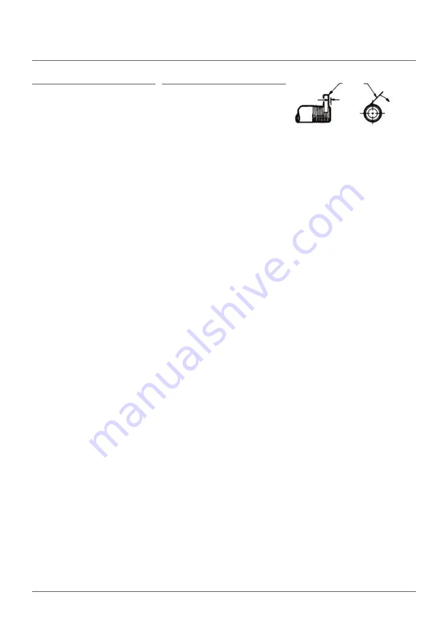
FIGURE 1
Tape
1-2
threads
Direction of
wrap
5.3 Operating
WARNING
Gagecock assemblies should be brought into
service slowly to avoid excessive shock or stress
on the tubular glass. Rapid pressurization of a
gagecock assembly can cause glass breakage
with resulting sudden release of pressure causing
serious personal injury or property damage.
To avoid excessive thermal shock or
mechanical stress on the tubular glass, the
connecting gagecocks should be opened
slightly and the gage temperature and pressure
allowed to equalize slowly with the vessel.
If the gagecocks are furnished with ball checks,
the gagecocks must be opened all the way after
the pressure and temperature have equalized
to permit operation of the automatic ball check
in the event of gage failure.
Summary of Contents for PENBERTHY N7 Series
Page 8: ...8 ...


