


16
ProLink
®
II Software for Micro Motion
®
Transmitters
Installation and Setup
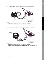
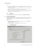
Figure 2-8
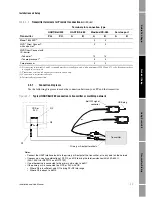
Modbus/RS-485 temporary connection to the service port
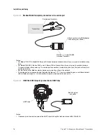
Figure 2-9
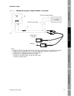
HART/Bell 202 temporary connection to HART clips
Attach serial port or USB adapter
if necessary (not shown)
Service port terminals
Transmitter
RS-232 <-> 2-wire RS-485
Interface Converter
Notes:
• For Model 1700/2700, Model 2400S, and LF-Series field-mount transmitters, the service port is available at any
time.
• For Model 1500/2500, Series 3000, and LF-Series DIN rail transmitters, the service port is available during a
10-second interval after power-up. If a service port connection is made during this time, the ports will remain in
service port mode.
• Ensure that no other Modbus master devices are currently active on the network.
• All service ports are accessed using the default address of 111. If you are connecting over a multidrop network
with multiple service ports, it is not possible to specify which device to connect to.
VIA
TOR
HART clips
Bell 202 signal
converter
Notes:
• If necessary, add resistance across the HART clips to bring the total resistance within 250–600
Ω
.
Summary of Contents for Network Router
Page 6: ...iv ProLink II Software for Micro Motion Transmitters ...
Page 12: ...6 ProLink II Software for Micro Motion Transmitters ...
Page 42: ...36 ProLink II Software for Micro Motion Transmitters ...
Page 64: ...58 ProLink II Software for Micro Motion Transmitters ...
Page 66: ...60 ProLink II Software for Micro Motion Transmitters ...
Page 70: ...64 ProLink II Software for Micro Motion Transmitters ...
Page 78: ...72 ProLink II Software for Micro Motion Transmitters ...
Page 94: ...88 ProLink II Software for Micro Motion Transmitters ...
Page 95: ......


