


Installation Drawings
23
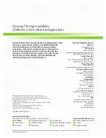
Figure 16 Liebert NXL Maintenance Bypass Cabinet control wire diagram with interlock
WIRE DIAGRAM WITH INTERLOCK
LOW VOLTAGE
TERMINAL STRIP
- TB1 -
21
20
19
18
17
16
15
14
13
12
11
10
9
8
7
6
5
4
3
2
1
EPO PB SW
TB1-1
TB1-2
TB1-4
TB1-5
TB1-6
TB1-7
TB1-8
TB1-9
TB1-10
TB1-11
TB1-12
TB1-13
TB1-14
TB1-15
TB1-16
Connections at UPS External
Interface Board (EIB)
TB0820
TB0824
TB0813
TB0811
TB0821
02-806708
1
3
TB0820
TB0821
1 3
1
3
1
3
TB0811
TB0813
1
3
TB0824
TB1-3
Table 5
Control wiring connections with interlock
From
To
Purpose
TB1-1
Customer EPO
Push Button Switch
EPO Signal
TB1-2
Customer EPO
Push Button Switch
TB1-3
TB0821-2
Maintenance Bypass
Enable Contacts
TB1-4
TB0821-1
TB1-5
TB0824-3
UPS REPO Contacts
TB1-6
TB0824-2
TB1-7
TB0824-1
TB1-8
TB0811-3
MIB Contacts
TB1-9
TB0811-2
TB1-10
TB0811-1
TB1-11
TB0813-3
MBB Contacts
TB1-12
TB0813-2
TB1-13
TB0813-1
TB1-14
TB0820-2
EPO Status Contacts
TB1-15
TB0820-1
TB1-16
TB0820-3
Summary of Contents for Liebert NXL 250
Page 34: ...Specifications 30 ...
Page 35: ......


