


Maintenance
Liebert
®
e
XM
™
74
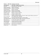
9.3.3 Torque Requirements
All electrical connections must be tight.
Tables 34
through
35
provide the torque values for the connections in the UPS and batteries. Use
these values unless the equipment is labeled otherwise.
9.4
Detecting Trouble
It is important that the operator check the instrument readings if abnormal equipment performance
is suspected. Any metered value that differs appreciably from normal could mean an impending
malfunction, and should be investigated.
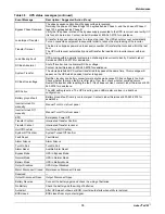
Items to check on the various UPS display screens include:
1. Output voltage of all phases should be within 2% of normal voltage. Output currents on each
phase should not normally differ by more than 20%. If a greater difference is noted, the load is
unbalanced and corrective action should be taken to redistribute the load, if possible.
2. If the UPS has not operated on battery power during the last 10 hours, the batteries should
require little charging current. Battery mimic should indicate normal DC voltage with relatively
little battery charge current.
3. Input current on each phase should be within 10% of the average input current. Alarm messages
indicate malfunction or impending malfunction. A daily check of the Operator Control Panel will
help to provide an early detection of problems. Refer to
Appendix B - UPS Status Messages
to
interpret alarm messages.
4. Tracing a problem to a particular section is facilitated by alarm messages and the metered
parameter indications. These are stored in the Status Reports and can be displayed at the
Operator Control Panel or at an optional terminal.
9.5
Reporting a Problem
If a problem occurs within the UPS, review all alarm messages along with other pertinent data. This
information should be given to the Liebert Service dispatcher. Call 1-800-LIEBERT to report a
problem or to request assistance.
9.6
Corrective Actions
Recommended corrective actions for each alarm message on the Operator Control Panel and the
Remote Alarm Status Panel may be found in
Appendix B - - UPS Status Messages
.
Table 34
Busbars—Power wiring
Bolt Shaft Size
Lb-in (Nm)
1/2" (M12)
428 (48)
Table 35
Terminal block with compression lugs—Control wiring
AWG Wire Size
or Range
Lb-in (Nm)
#22 - #14
3.5 to 5.3
(0.4 to 0.6)
NOTE
If the UPS system has a blown fuse, the cause should be determined before you replace the fuse.
Contact Liebert Global Services.
Summary of Contents for Liebert eXM
Page 1: ...Liebert eXM User Manual 60 100kVA 50 60Hz ...
Page 2: ......
Page 8: ...vi ...
Page 89: ...Maintenance 81 Liebert eXM NOTES ...
Page 90: ...Maintenance Liebert eXM 82 ...
Page 91: ......