background image

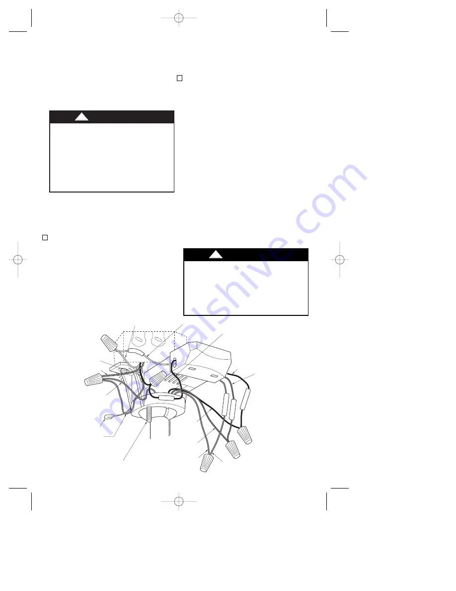
1. Position the supply wires to the left side

of the outlet box (Figure 14); position
the fan wires to the right side. Partially
insert the remote control receiver (flat
side up) until one end rests on the
hanger ball as shown in Figure 14.

NOTE: Make all wiring connections
using wire connectors (supplied). Make
sure that all connections are tight,

How to Wire

Your Ceiling Fan

Turning off wall switch is not
sufficient. To avoid possible
electrical shock, be sure electricity is
turned off at the main fuse box
before wiring. All wiring must be in
accordance with National and Local
codes and the ceiling fan must be
properly grounded as a precaution
against possible electrical shock.

!

WARNING

Check to see that all connections are
tight, including ground, and that no
bare wire is visible at the wire
connectors, except for the ground
wire. Do not operate fan until blades
are in place. Noise and fan damage
could result.

!

WARNING

If you feel that you do not have enough
electrical wiring knowledge or
experience, have your fan installed by a
licensed electrician. 

including ground, and that no bare wire
is visible at the wire connectors, except
for the ground wire.
2. 
Refer to Figures 14 and 15 and connect

the receiver wires to the supply wires
and the fan motor wires as follows:

a. Securely connect the green grounding

wires from the hanger ball and the
hanger bracket to the supply grounding
conductor (this may be a bare wire or a
wire with green insulation).

b. Securely connect the supply white

(neutral) wire to the receiver white
(AC IN N) wire.

c. Securely connect the supply black wire

(hot) wire to the receiver black (AC IN
L) wire.

d. Securely connect the fan motor white

wire to the receiver white (TO MOTOR
N) wire.

e. Securely connect the fan motor black

wire to the receiver red (TO MOTOR L)
wire.

f. Securely connect the fan motor blue

wire to the receiver blue (FOR
LIGHT) wire.

GREEN GROUND 
WIRE FROM 
HANGER BRACKET

RECEIVER RED WIRE

RECEIVER WHITE WIRE

FAN WHITE WIRE

FAN 
BLACK 
WIRE

ANTENNA

AC IN N

AC IN L

FOR LIGHT

T

O

 MOT

OR N

RECEIVER BLUE 
WIRE

RECEIVER 
BLACK WIRE

RECEIVER WHITE 
WIRE

SUPPLY WHITE WIRE 
(NEUTRAL)

SUPPLY BLACK 
WIRE (HOT)

GROUND WIRE

GREEN GROUND 
WIRE FROM 
HANGER BALL

FAN BLUE WIRE

1-1/4" THREADED 
STUD (2)

T

O

 MOT

OR L

Figure 14

11

CAUTION: To reduce the risk of
electrical shock, disconnect the
electrical supply circuit before
installing the fan, light kit or receiver.

U.L. Model No.: CF220

BP7360 JULIANNE  9/19/07  11:15 AM  Page 11

Summary of Contents for JULIANNE CF220AGW00

Page 1: ...RUCTIONS Net Weight 33 7 Lbs JULIANNE Ceiling Fan Owner s Manual CF220GBZ00 Gilded Bronze with Dark Cherry Walnut Blades CF220GLZ00 Gilded Silver with Natural Cherry Mahogany Blades CF220AGW00 Aged Walnut with Teak Mahogany Blades Model Numbers BP7360 JULIANNE 9 19 07 11 15 AM Page 1 ...

Page 2: ...box Most outlet boxes commonly used for support of light fixtures are not acceptable for fan support and may need to be replaced Consult a qualified electrician if in doubt 4 The longer downrod furnished with the fan provides the minimum recommended floor to fan blade clearance for a 9 foot ceiling The 6 downrod supplied must be used for an 8 foot ceiling 5 The fan must be mounted with the fan bla...

Page 3: ...ur ceiling fan refer to section on proper method of wiring your fan page 11 If you feel you do not have enough wiring knowledge or experience have your fan installed by a licensed electrician WARNING Unpacking Instructions For your convenience check off boxes are provided next to each step As each step is completed place a check mark in the box This will insure that all steps have been completed a...

Page 4: ...her 12 One metal washer 13 One rubber washer 14 One hex wrench NOTE Place the parts from the loose parts bags in a small container to keep them from being lost 2 Remove the fan motor and housing assembly from the protective plastic bag Place the fan assembly into the lower foam pad with the bottom of the motor facing up The lower foam pad serves as a holder for the fan during the first stages of a...

Page 5: ...rocedures IMPORTANT Before assembling your ceiling fan refer to sections Setting Operating Frequency of Wall Control and Receiver and Installation of Wall Control page 13 These sections instruct you how to a Set the operating frequency of the fan light wall control and the remote control receiver and b Install the fan light wall control in the wall box You will then be ready to proceed with the as...

Page 6: ...bly Figure 3 Connect the black wire from the light fitter to the blue wire in the switch cup 6 FAN BLADE BLADE FLANGE 10 24 X 8mm PAN HEAD SCREW 3 FLAT WASHER 3 Figure 1 NOTCH 1 4 20 x 13mm OVAL HEAD SCREWS 2 BLADE FLANGE MOTOR HUB SWITCH CUP PLATE Figure 2 SWITCH CUP ASSEMBLY WHITE WIRE 1 8 27 NUT LOCKWASHER BLUE WIRE BLACK WIRE WHITE WIRE DECORATIVE RING LIGHT FITTER ASSEMBLY LIGHT FITTER Figure...

Page 7: ...crew in the remaining hole in the switch cup Figure 5 CAUTION Before installing and tightening the screws be sure there are no wires pinched between the switch cup plate and switch cup assembly 7 SWITCH CUP ASSEMBLY SWITCH CUP CONNECTOR MOTOR CONNECTOR 8 32 x 7mm PAN HEAD SCREW 2 Figure 4 10 Position the top and bottom halves of the styrofoam packaging side by side on the floor with a six to eight...

Page 8: ...re properly installed as shown in Figure 8 could result in the fan falling PIN HANGER BALL SETSCREW DOWNROD Figure 7 11 Remove the hanger ball by loosening the setscrew in the hanger ball until the ball falls freely down the downrod Figure 7 Remove the pin from the downrod then remove the hanger ball Retain the pin and hanger ball for reinstallation in step 18 NOTE If you have an eight foot ceilin...

Page 9: ... back insulation 1 2 from end of leads 20 You have now completed the initial assembly of your new ceiling fan You can now proceed with hanging and wiring your fan 15 Unscrew the three scroll retaining screws from the scroll collar Using the hex wrench supplied unscrew the setscrew in the scroll collar until it clears the inside of the collar Slide the collar over the downrod Figure 9 and position ...

Page 10: ...d assembly and hanger bracket WARNING TWO SCREWS SUPPLIED WITH OUTLET BOX HANGER BRACKET TAB OUTLET BOX NOTE CEILING COVER SUPPL Y WIRES AND FAN WIRES OMITTED FOR CLARITY OUTLET BOX HANGER BRACKET HANGER BALL DOWNROD ASSEMBLY Figure 12 Figure 13 How to Hang Your Ceiling Fan The fan must be hung with at least 7 of clearance from floor to blades Figure 11 WARNING The outlet box and joist must be sec...

Page 11: ...nectors except for the ground wire 2 Refer to Figures 14 and 15 and connect the receiver wires to the supply wires and the fan motor wires as follows a Securely connect the green grounding wires from the hanger ball and the hanger bracket to the supply grounding conductor this may be a bare wire or a wire with green insulation b Securely connect the supply white neutral wire to the receiver white ...

Page 12: ...N WIRE GROUND FROM HANGER BALL AND HANGER BRACKET TWO CONDUCTOR CABLE WITH GROUND BLACK HOT WHITE GROUND TO 120 VOLT SUPPLY WHITE BLUE WHITE BLUE EMERSON HI MED LOW FAN OFF LIGHT ON OFF Figure 15 3 Push the wires and connectors up into the outlet box while inserting the receiver fully into the hanger bracket Position the antenna wire on top of the receiver 4 Screw the two 1 1 4 threaded studs supp...

Page 13: ...eceiver have code switches which must be set in one of 16 possible code combinations The four levers numbered 1 2 3 and 4 on the switches are factory set in the ON up position Change the switch settings as follows 1 Slide the four switch levers in the wall control to your choice of ON up or down positions Use a ball point pen or small screwdriver and slide the levers firmly up or down 2 In the rec...

Page 14: ...wire in wall box Securely connect wires with wire connector supplied 6 Screw wall control into wall box and install decorator style faceplate included Leave wall control in OFF mode until fan installation is completed 7 Refer to page 5 and complete the ceiling fan installation Do not connect any neutral white wire to this control Incorrect wiring will damage this control WARNING Do not connect any...

Page 15: ...e electricity on at the service panel NOTE Make sure that the ON OFF slide switch on the Fan Light Wall Control is in the ON position 2 To set the desired fan speed press the HI MED or LOW buttons to operate your fan on high medium or low speed Figure 23 3 To turn your fan off press the OFF button REVERSING SWITCH EMERSON HI MED LOW FAN OFF LIGHT ON OFF Figure 23 Figure 24 4 To set the level of li...

Page 16: ...e in a residential installation This equipment generates uses and can radiate radio frequency energy and if not installed and used in accordance with the instructions may cause harmful interference to radio communications However there is no guarantee that interference will not occur in a particular installation If this equipment does cause harmful interference to radio or television reception whi...

Page 17: ...housing 4 Check to make sure all screws in motor housing are snug not over tight 3 Fan wobbles 1 Setscrews in motor coupling are 1 Raise coupling cover and tighten excessively not tightened securely setscrews securely 2 Setscrew in the hanger ball 2 Tighten the setscrew in the downrod assembly is loose hanger ball downrod assembly 3 Screws securing fan blade 3 Check to be sure screws which flanges...

Page 18: ...ng material be certain all parts have been removed HOW TO ORDER REPAIR PARTS WHEN ORDERING REPAIR PARTS ALWAYS GIVE THE FOLLOWING INFORMATION PART NUMBER NAME OF ITEM PART DESCRIPTION MODEL NUMBER The model number of your Fan will be found on a label attached to the top housing For repair parts phone 1 800 654 3545 18 U L Model No CF220 BP7360 JULIANNE 9 19 07 11 15 AM Page 18 ...

Page 19: ...oll 763027 AGW 763027 GLZ 763027 GBZ 21 Collar Scroll 22 Screw Scroll Retaining 3 23 Cover Coupling 763029 AGW 763029 GLZ 763029 GBZ 24 Housing Switch 763036 AGW 763036 GLZ 763036 GBZ 25 Harness Wiring 763037 763037 763037 26 Fitter Assembly Light 763038 763038 763038 27 Ring Assembly Decorative 763040 AGW 763040 GLZ 763040 GBZ 28 Glass Lower 763039 763039 763039 29 Flange Set full set for one fan...

Page 20: ...actory or authorized service center Your Emerson Air Comfort Ceiling Fan should be properly packed to avoid damage in transit since we will not be responsible for any such damage What Is Not Covered The glass globes and light bulbs of your ceiling fan are not covered by this warranty This warranty also does not cover any defects malfunctions or failures caused by Repairs by persons not authorized ...

Reviews: