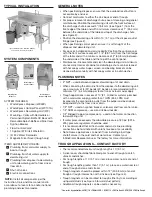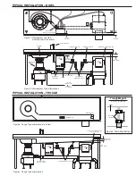
TYPICAL INSTALLATION – BOWL
TYPICAL INSTALLATION – TROUGH
Figure 1. WasteXpress Top View
with Electrical Connections
Flow Control Valve
WasteXpress
Disposer
Sink Bowl
Syphon Breaker
Cold Water Solenoid
Hot Water Solenoid WasteXpress Dewatering Unit
Shut Off Valve
(supplied by others)
1-1/2" min
(38.1 mm
min)
1" min
(25.4 mm min)
45˚ bend shown
(max of 4 can be used)
3"
(76.2 mm)
1-1/2"
(38.1 mm)
Figure 2. WasteXpress Typical Installation
WasteXpress
Control Panel
10 max
(3.1 m max)
18" min
(0.46 m min)
Power
Trough Flow
Water Nozzle
Recommended
Magnet Location
Optional Magnet Location
Connect Cold Water Supply
1" min
(25.4 mm min)
1" (25.4 mm) min,
3" (76.2 mm) max
to end of Trough
Figure 4. Trough Typical Installation
Figure 3. Trough Typical Installation Top View
Trough
Trough
Optional Magnet Location
Recommended Magnet Location
Mounting
Brackets
6"
2–3/8"
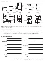
Figure 1: Viewing From Bottom
Figure 2: Trough Magnet Positions
Trough Silver Saver Kit
(#13983)
Part No. 13986 January 2008
Installation Instructions
1. Determine best place for magnet(s)
(See Figure 2).
2. Place magnet on underside of trough with
magnetic pull toward sink bowl.
3. Place one mounting bracket over each end
of magnet (See Figure 1). Shoot weld studs
and secure mounting brackets with nuts.
NOTE:
Trough magnets should be placed
within 12" from end of trough or
intersection of trough and sink bowl.
NOTE:
Additional magnets should
be evenly spaced over remaining
trough area.
Trough Magnet
As Viewed From Bottom
Figure 5. Weld Stud Pattern


