

GENERAL NOTES
• When positioning disposer, ensure that the overload reset button is
accessible by end user.
• Connect cold water to either the sink bowl or end of trough.
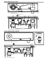
• For proper removal of discharge chute, ease of cleaning, and general
maintenance: Position the dewatering unit with the front surface of
the discharge chute recessed 3" (76.2 mm) (see Figure 1) from the
front edge of the table and with a minimum clearance of 1" (25.4 mm)
between the underside of the table and top of the discharge chute
(see Figure 2).
• Position the dewatering unit within 10' (3.1 m) of the disposer outlet
flange (see Figure 2).
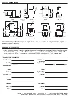
• When positioning control panel, ensure it is within sight of the
disposer and dewatering unit.
• For ease of installation and serviceability: Position the control panel
with the front surface recessed 1-1/2" (38.1 mm) from the front edge
of the table and with a minimum clearance of 2" (50.8 mm) between
the underside of the table and the top of the control panel.
• Maintenance: Disassemble and clean the dewatering unit a minimum
of once daily. Interior of cabinet and discharge chute can be cleaned
with hot soapy water. Auger, screen, and bearing bracket can be
cleaned either manually with hot soapy water or in a dishwasher.
PLUMBING NOTES
• 2" NPT – used between disposer, dewatering unit, and drain.
• When connecting the drain line from the disposer to the dewatering unit,
use a maximum of (4) 90° bends (45° bends are recommended) with a
minimum 1/4" (6.4 mm) drop per foot of run or as local codes apply.
• Trough applications in excess of 10' (3.1 m) and/or systems plumbed
with a cold water supply greater than 7 GPM (26.5 LPM) must
incorporate the second drain outlet from the pulper and be drained
independently to the floor sink or drain.
• 1/2" NPT – used on syphon breaker, solenoid, and flow control valve.
• 1/2" NOM compression – used on sink bowl nozzles.
• 1/2" Ridged Copper (compression) – used on hot water connection
to dewatering unit.
• If water pressure exceeds the allowable pressure of 80 psi (551.6
kPa), pressure regulators should be used.
• It is recommended that all fresh water and waste line plumbing
connections be terminated with unions for ease of serviceability.
• Note: Some applications can benefit from installing a ball type
shutoff valves in the cold and hot water lines. Contact your
InSinkErator Representative or the factory for more information.
TROUGH APPLICATIONS – CONTACT FACTORY
• The recommended maximum trough length is 10' (3.1 m).
• A silver saver should be fabricated prior to end of trough to catch
utensils and dishes.
• For trough lengths of 10' (3.1 m) or less place water nozzle at end of
trough.
• For trough lengths greater than 10' (3.1 m), place one water nozzle at
end of trough and one mid stream.
• Trough magnets should be placed within 12" (304.8 mm) of end of
trough or trough intersection with sink bowl (see Figure 4).
• Trough magnets can be mounted to trough either by tack welding or
using weld studs (see Figure 5 for weld stud pattern).
• Additional trough magnets can be used as necessary.
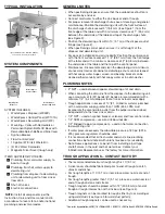
TYPICAL INSTALLATION
SYSTEM COMPONENTS
WasteXpress
Disposer
WasteXpress
Control Panel
WasteXpress
Dewatering Unit
SYSTEM INCLUDES:
• WasteXpress Disposer (WX500)
• WasteXpress Control Panel (WX101A)
• WasteXpress Dewatering Unit (WX)
• Mounting – Collar with Removable or
Permanent Splash Baffle OR Bowl with
Removable Splash Baffle and Sink Cover
• Syphon Breaker
• Flow Control Valve*
• 10 gallon (37.9 liter) Waste Bin
• (2) 24V Water Solenoids
• Magnetic Silver Saver (trough only)
ITEMS SUPPLIED BY OTHERS:
Plumbing from cold water supply to
bowl or trough
Plumbing from hot water supply to
dewatering unit
Plumbing from disposer to dewatering
unit or dewatering unit to floor sink or
floor drain
Shut-off valves
Electrical connections
NOTE:
Install all components per the
Instruction, Care and Use manual and in
accordance to local, state, and/or national
plumbing and electrical codes.
Typical installation shown. Dish table, plumbing,
and electrical connections not included.
*Size varies by application: 2 GPM (7.6 LPM) for LEED, 3 GPM (11.4 LPM) for Bowl, 5 GPM (18.9 LPM) for Trough


