


4
IPMC7126E/7616E I/O Module Installation and Use (6806800A45B)
25
4
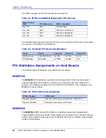
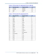
Connector Pin Assignments
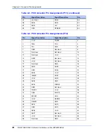
This chapter provides connector pin assignments for the IPMC712 and IPMC761 modules.
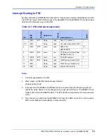
IPMC712 Connector
This connector provides the on-board interface of the IPMC712 I/O signals. The pin
assignments for this connector are as follows:
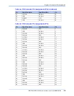
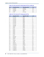
Table 4-1. IPMC712 Connector
Pin
Signal Description
Signal Description
Pin
1
I2CSCL
I2CSDA
2
3
GND
GND
4
5
JDB8#
GND
6
7
GND
JDB9#
8
9
JDB10#
+3.3V
10
11
+3.3V
JDB11#
12
13
JDB12#
GND
14
15
GND
JDB13#
16
17
JDB14#
+3.3V
18
19
+3.3V
JDB15#
20
21
JDBP1#
GND
22
23
GND
LANINT2_L
24
25
PIB_INT
+3.3V
26
27
+3.3V
PIB_PMCREQ#
28
29
PIB_PMCGNT#
GND
30
31
GND
+3.3V
32
33
+5.0v
+5.0v
34
35
GND
GND
36
37
+5.0v
+5.0v
38
39
GND
GND
40
Summary of Contents for I/O MODULE IPMC7126E
Page 1: ...i IPMC7126E 7616E I O Module Installation and Use 6806800A45B September 2008 Edition ...
Page 8: ...IPMC7126E 7616E I O Module Installation and Use 6806800A45B List of Figures viii ...
Page 10: ...IPMC7126E 7616E I O Module Installation and Use 6806800A45B List of Tables x ...
Page 14: ...IPMC7126E 7616E I O Module Installation and Use 6806800A45B About This Manual xiv ...
Page 24: ...IPMC7126E 7616E I O Module Installation and Use 6806800A45B Chapter 1 Product Features 10 ...
Page 52: ......