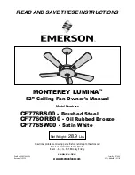
tight against the pin and securely tight-
en the setscrew in the hanger ball.
A loose setscrew could create fan
wobble.
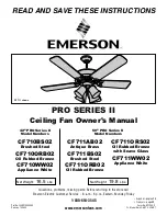
DOWNROD
DECORATIVE
COVER
GROMMET
DECORATIVE
SCROLL
ASSEMBLY
40-WATT CANDELABRA
BASE ROUND BULB (3)
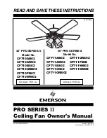
10. Tighten the setscrews (Figure 6) secure-
ly while pulling up on the downrod.
NOTE: The setscrews must be properly
installed as described above, or fan
wobble could result.
NOTE: If you installed the 3-1/2” down-
rod, the decorative scroll assembly and
decorative cover will not be installed.
Disregard the next step.
11. Make sure the grommets are properly
installed in the decorative scroll
assembly and in the decorative cover.
Slide the decorative scroll over the
downrod until it rests on the motor
housing. (Figure 7). Then slide the
decorative cover over the downrod
until it rests on the top of the decora-
tive scroll.
12. Place the ceiling cover over the down-
rod. Then reinstall the hanger ball
(Figure 8) on the downrod as follows.
Route the four 80” motor leads through
the hanger ball and slide the hanger
ball over the downrod. Position the pin
through the two holes in the downrod
and align the hanger ball so the pin is
captured in the groove in the top of the
hanger ball. Pull the hanger ball up
DOWNROD
MOTOR
COUPLING
HAIRPIN
CLIP
SETSCREW (2)
CLEVIS PIN
Figure 6
Figure 7
Figure 8
7
It is critical that the clevis pin in the
motor coupling is properly installed
and the setscrews securely tight-
ened. Failure to verify that the pin
and setscrews are properly installed
(as shown in Figure 5) could result in
the fan falling.
!
WARNING
HANGER BALL
PIN
CEILING COVER
SETSCREW
DOWNROD
It is critical that the pin in the hanger
ball is properly installed and the
setscrew securely tightened. Failure
to verify that the pin and setscrew
are properly installed could result in
the fan falling.
!
WARNING
BP7283, High Country, KF160 7/31/06 10:54 AM Page 7