Y692VB Series
2
!
WARNING
Personal injury, equipment damage
or leakage due to escaping fluid or
bursting of pressure-containing parts
may result if this vacuum breaker is
overpressured or is installed where
service conditions could exceed the
limits given in the Specifications
section or where conditions exceed
any ratings of the adjacent piping or
piping connections.
To avoid such injury or damage, provide
pressure-relieving or pressure-limiting
devices (as required by the appropriate
code, regulation or standard) to
prevent service conditions from
exceeding limits.
Additionally, physical damage to the
vacuum breaker could result in personal
injury and property damage due to
escaping fluid. To avoid such injury and
damage, install the vacuum breaker in a
safe location.
Clean out all pipelines before installation of the
vacuum breaker and check to be sure the vacuum
breaker has not been damaged or has collected
foreign material during shipping. For NPT bodies,
apply pipe compound to the external pipe threads.
For flanged bodies, use suitable line gaskets and
approved piping and bolting practices. Install the
vacuum breaker in any position desired, unless
otherwise specified, but be sure flow through the body
is in the direction indicated by the arrow on the body.
Startup
The vacuum breaker is factory set at approximately
the midpoint of the spring range or the pressure
requested, so an initial adjustment may be required
to give the desired results. With proper installation
completed and vacuum breakers properly adjusted,
slowly introduce inlet pressure. The unit takes
control when vacuum is established. This equipment
is suitable for the vacuum control pressure range
stamped on the nameplate.
Adjustment
To adjust the pressure setting, remove the closing cap
and turn the adjusting nut clockwise to increase the
pressure setting or counterclockwise to decrease the
setting. Replace the closing cap after adjustment. The
closing cap may be wired to the hole provided in the
spring case to discourage tampering.
Taking Out of Service (Shutdown)
To avoid personal injury resulting from
sudden release of pressure, isolate the
vacuum breaker from all pressure before
attempting disassembly.
To shut down the unit, close the upstream shut-off
valve, and then close the downstream shut-off valve to
vent the equipment properly. Next, open the vent valve
between the equipment and the downstream shut-off
valve nearest to it. All pressure between these shut-off
valves is released through the open vent valve.
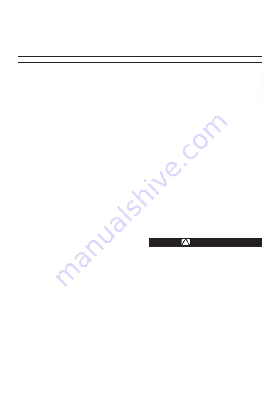
Table 1
. Vacuum Pressure Information
VACUUM CONTROL PRESSURE RANGE
(1)
CHANGE IN VACUUM CONTROL PRESSURE TO REACH WIDE-OPEN
mbar
in. w.c.
mbar
in. w.c.
2 to 7
(2)
7 to 20
(2)
20 to 40
40 to 80
17 mbar to 0.21 bar
1 to 3
3 to 8
8 to 16
16 to 32
0.25 to 3 psig
3
10
13
26
0.14 bar
1.2
4.0
5.0
10.5
2 psig
1. Pressure ranges are based on the spring case pointing up. Pointing the spring case down increases the pressure range 4 mbar / 1.7 in. w.c..
(Example: 2 to 7 mbar / 1 to 3 in. w.c. changes to 7 to 12 mbar / 2.7 to 4.7 in. w.c..
2. Do not use fluorocarbon (FKM) with these springs at diaphragm temperatures lower than 4°C / 40°F.


