background image

Type OSE

6

C57

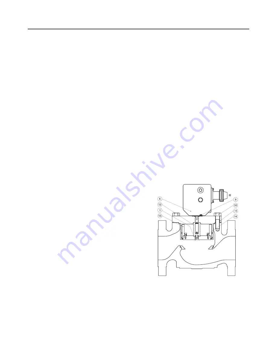
Figure 7.

 Type OSE - Commissioning Schematic

Commissioning 

(max. only or max. & min.)

• 

Inlet valve


 Open slowly

• 

Slam-shut bypass


 Open slowly (stage 2)

• 

Regulator


 Put into operation (see corresponding manual)

• 

1

st

 release relay stage
 

 Set (Stage 1)

• 

Slam shut valve plug


 Open (Stage 3)

• 

Outlet valve


 Open slowly

The equipment is commissioned

After checking and commissioning the release relay it is 

recommended to seal it

MaiNTENaNCE

Servicing Check

recommended frequency:

• 

Twice yearly minimum

Verification:

• 

Tripping and tripping value

• 

Slam-shut tightness

Departure positions

• 

Inlet valve 

→ 

Open

• 

Outlet valve 

→ 

Open

• 

Slam-shut 

→ 

Open

• 

Regulator 

→ 

In operation

Inlet and outlet sides of regulator under pressure

Tripping verification

• 

Inlet valve 

→ 

Closed

• 

Outlet valve 

→ 

Closed

• 

Regulator 

Increase setpoint to reach tripping 


(without exceeding the outlet limits)

Disassembly

recommended frequency

:

• 

Every 4 to 6 years (or less depending on  

operating conditions)

• 

In the case of BMS 162 or 071, it is highly recommended to 

check the condition of the diaphragm once yearly

Verification

:

• 

Condition of O-rings, diaphragm, and lubrication

replacement

:

• 

O-rings, diaphragm

Tools

:

• 

Spanners 10, 13, six-sided wrench 6

• 

Spanners According to DN size

• 

Emerson spanner ref. 197125 (bypass and pin disassembly)

•  Valve plug closed
• 

Close inlet and outlet valves

• 

bleed off outlet pressure

• 

bleed off inlet pressure

• 

Unscrew impulse connection 

iS

• 

Remove BM cover (key 8)

• 

Unscrew fastening screw (key 9)

• 

Remove cap

• 

Remove BM

• 

Unscrew screws (key 10)

• 

Remove bonnet (key 11) 

• 

Remove spring (rep. 12) and slam-shut valve plug (key 13)

• 

Unscrew bypass (key 1)

• 

Unscrew screws (key 14) (DN 100 and 150)

The removal of the orifice (not recommended) requires a 

special extraction tool

reassembly

• 

Perform the above operations in reverse order (respect 

tightening torques)

• 

Replace O-rings at each disassembly

• 

The valve plug should be maintained in an upright position 

using the packing gland to facilitate it’s removal

• 

Precaution should be taken when removing or replacing 

the valve plug to avoid damaging the segments

Summary of Contents for Fisher OSE

Page 1: ...interior Ø 8 10 mm Safety contact See D103683X012 manual INTRODUCTION Scope of the Manual This manual provides installation start up maintenance and parts ordering information for the Type OSE Slam Shut Valve Information on other equipment used with this slam shut valve is found in separate manuals Product Description The Type OSE Slam Shut Valve protects transmission and distribution networks or ...

Page 2: ...bel Figure 2 Accuracy AG 2 5 5 Piston Setpoint range Wdu Wdo 0 010 à 100 bar Response time ta 1 s Max Differential valve closed P max 100 bar Max Differential valve open P max See Table 2 Rearming Manually after rectification of fault Position indicator On mechanism box Fluid Group 1 and 2 according to PED 2014 68 UE 1st and 2nd family gas according to EN 437 or other gases compressed air nitrogen...

Page 3: ...0 62 334 220 124 17 50 20 150 254 76 346 220 152 26 50 300 267 83 346 220 165 29 100 600 287 83 346 220 165 32 80 20 150 298 95 380 220 190 43 50 300 318 105 380 220 210 48 100 600 337 105 380 220 210 55 100 20 150 353 114 420 220 229 74 50 300 368 127 420 220 154 82 100 600 394 137 420 220 273 98 150 20 150 451 140 424 220 357 150 50 300 473 159 424 220 357 166 100 600 508 178 424 220 357 202 C53...

Page 4: ...e of Operation The slam shut valve is installed on the inlet side of the regulator on the horizontal pipeline The mechanism box should be situated on top see above schematic or on top for versions DN 25 50 80 Installation according to EN12186 is recommended Install according to direction of the fluid flow see arrow When assembling with adjacent elements care must be taken not to create pressure fo...

Page 5: ...be checked periodically commissioning warning All interventions on the equipment should only be performed by qualified and trained personnel Preliminary verifications Start up positions Inlet and outlet valves Closed Verify absence of pressure between inlet and outlet valves Slam shut valve plug Closed Impulse isolation valve Closed Impulse atmospheric valve Open Setpoint Verification Using the at...

Page 6: ...operating conditions In the case of BMS 162 or 071 it is highly recommended to check the condition of the diaphragm once yearly Verification Condition of O rings diaphragm and lubrication Replacement O rings diaphragm Tools Spanners 10 13 six sided wrench 6 Spanners According to DN size Emerson spanner ref 197125 bypass and pin disassembly Valve plug closed Close inlet and outlet valves Bleed off ...

Page 7: ...ve closes Operating correctly Observe the evolution of the outlet pressure check tightness If the outlet pressure in the slam shut is decreases External leak Locate and seal the leak or contact after sales If the outlet pressure in the slam shut is constant Bleed off the outlet side of the regulator Observe the evolution of the outlet pressure check tightness If the outlet pressure increases Inter...

Page 8: ...implied regarding the products or services described herein or their use or applicability All sales are governed by our terms and conditions which are available on request We reserve the right to modify or improve the designs or specifications of our products at any time without notice Emerson Process Management Regulator Technologies Inc does not assume responsibility for the selection use or mai...

Reviews: