


Instruction Manual
D103425X012
546NS Transducer
June 2021
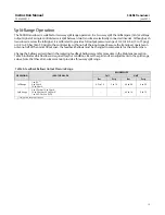
8
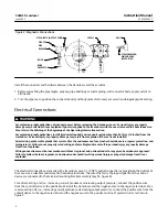
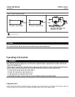
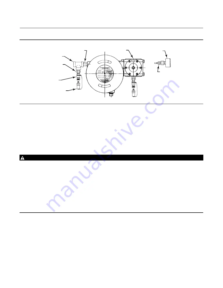
Figure 2. Diagnostic Connections
PIPE NIPPLE (OUTPUT CONN)
12B8041‐B
A6072‐1
PIPE TEE
PIPE
BUSHING
BODY
BODY
PROTECTOR
SUPPLY
GAUGE
STEM PROVIDED
WHEN GAUGE
IS SPECIFIED
Install the connectors and hardware between the transducer and the actuator.
1. Before assembling the pipe nipple, pipe tee, pipe bushings, actuator piping, and connector body, apply sealant to
all threads.
2. Turn the pipe tee to position the connector body and body protector for easy access when doing diagnostic testing.
Electrical Connections
WARNING
For explosion‐proof applications, disconnect power before removing the transducer cover. Personal injury or property
damage may result from fire or explosion if power is applied to the transducer with the cover removed in a hazardous area.
Also refer to the Warning at the beginning of the Operating Information section.
For explosion‐proof applications, install rigid metal conduit and a conduit seal no more than 457 mm (18 inches) from the
transducer. Personal injury or property damage may result from explosion if the seal is not installed.
Select wiring and/or cable glands that are rated for the environment of use (such as hazardous area, ingress protection, and
temperature). Failure to use properly rated wiring and/or cable glands can result in personal injury or property damage
from fire or explosion.
Wiring connections must be in accordance with local, regional, and national codes for any given hazardous are approval.
Failure to follow the local, regional, and national codes could result in personal injury or property damage from fire or
explosion.
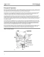
The electrical connections are made in the transducer case. A 1/2 NPT conduit connection is provided in the bottom of
the case. Use a suitable conduit seal for hazardous locations. The wires that carry the input signal from the control
device are connected to the terminal mounting bracket assembly (key 53, figure 8).
For a direct‐acting unit (i.e., increasing current produces an increasing output pressure), connect the positive wire
from the control device to the positive terminal of the transducer and the negative wire to the negative terminal. For a
reverse‐acting unit (i.e., increasing current produces a decreasing output pressure), connect the positive wire from the
control device to the negative terminal and the negative wire to the positive terminal. Typical circuits are shown in
figure 3.


