background image

Type 310A

9

Install the Type 310A-32A-32A into the pipeline using 

adequate gaskets for flanged regulator units and good 

piping technique.  Be sure to provide suitable pressure 

gauges where appropriate, block valves, bypass 

valves and piping, and bleed valves to permit safe 

and easy maintenance of both the working monitor 

regulator and the second-stage working regulator.  Be 

sure flow will be in the direction indicated by the arrow 

cast on the body.
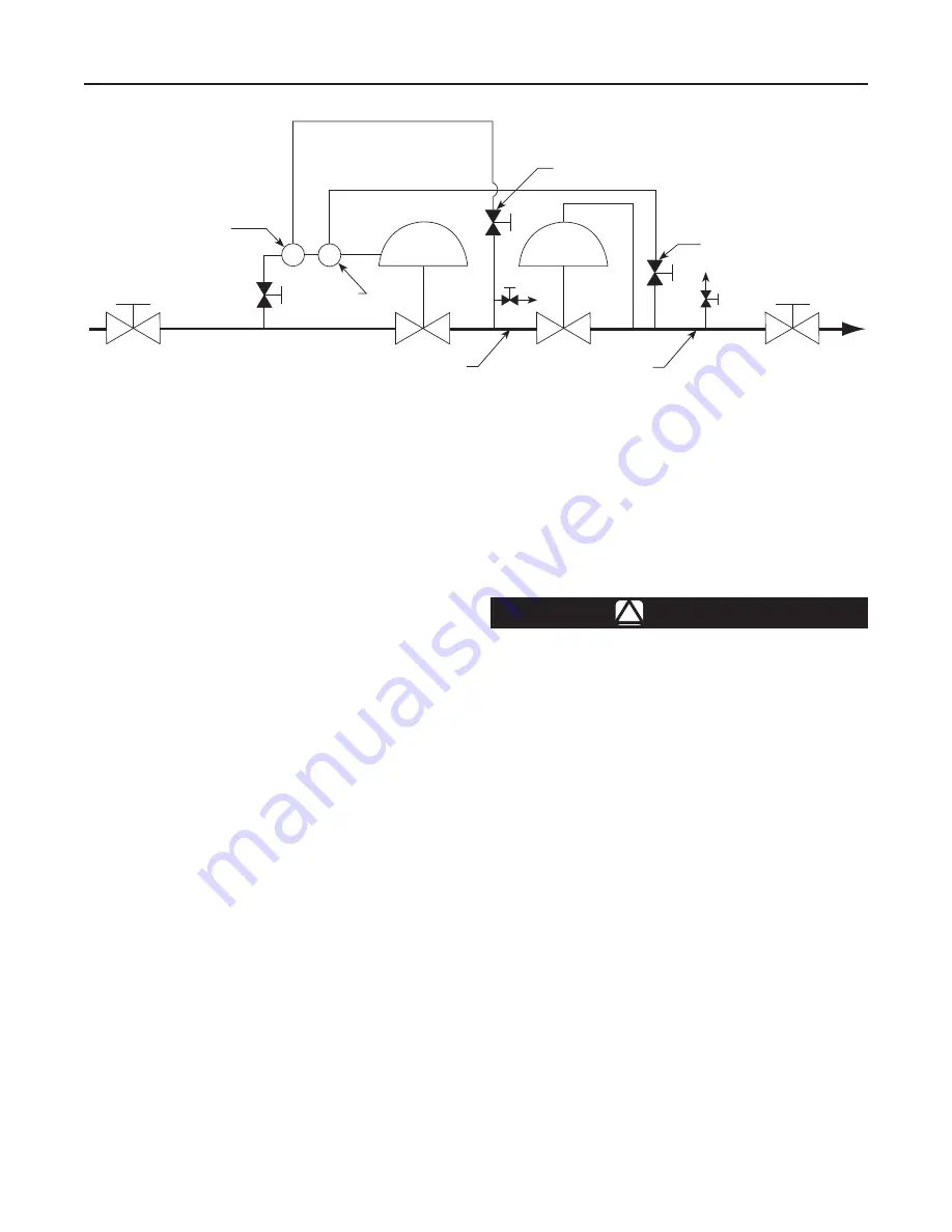
Refer to the Figure 8 schematic and Figure 14, and 

proceed in the following steps.
  1.  Attach the intermediate pressure control line  

      (1/2 NPT pipe) between the 1/2 NPT pipe tee  

    (key 72, Figure 14) and the intermediate pressure  

      portion of the downstream piping.  Install hand  

      valve B in this line.
  2.  Connect 1/2 NPT distribution pressure control  

       line piping between the 1/2 NPT connection  

       in the mounting bracket (key 45, Figure 14) and  

       the pipeline downstream of the second-stage  

       working regulator.  Include hand valve A in this  

       control line.

note

Each pilot has a nameplate identifying it 

as the working or monitor pilot.

  3.  Pipe the pilot supply line to 1/4 NPT connection in  

       the back of the working pilot body.  Supply pressure  

       should be filtered if excess dirt or condensate is  

       present in the supply gas.
  4.


Install downstream working regulator per guidelines.

Startup

  1.  Before introducing any pressure to the unit,  

      close hand valve A in the distribution pressure  

      control line and hand valve B in the intermediate  

      pressure control line.

CAuTIOn

Pilot supply pressure must be 

introduced into the regulator prior 

to introduction of any downstream 

pressure or internal damage may occur 

due to reverse pressurization of the 

pilot and main valve components.  Pilot 

supply pressure must be at least 

15 psi (1,0 bar) greater than control 

pressure for proper operation.

  2.  Slowly open the hand valve in the pilot supply line.
  3.  Slowly open the upstream block valve and partially  

       open the downstream block valve for minimum flow.
  4.  Slowly open hand valve B and allow the  

       intermediate pressure to increase to the 

       working pilot setting.
  5.  Put the second-stage working regulator into         

       operation according to recommended procedures  

       and instructions furnished with the second-stage  

       working regulator.
  6.  After the distribution pressure has been established  

      slowly open hand valve A.

Figure 8. 

Typical Working Monitor Installation

A0714_2

WORKIng PILOT

MOnITORIng 

PILOT

hAnD VALVE B

hAnD VALVE A

DISTRIBuTIOn PRESSuRE

InTERMEDIATE PRESSuRE

Summary of Contents for Fisher 310A-32A

Page 1: ...This Instruction Manual provides installation maintenance and parts ordering information for the Type 310A 32A pilot operated pressure reducing regulator and the Type 310A 32A 32A working monitor regulator Information on equipment used with this regulator is found in separate manuals Description The Type 310A 32A pilot operated pressure reducing regulator includes a single Type 32A pilot mounted o...

Page 2: ...F 29 to 66 C Fluorocarbon FKM with Wiper Ring 0 to 150 F 18 to 66 C Fluorocarbon FKM without Wiper Ring 0 to 300 F 18 to 149 C Options Main valve body without pilot for on off service Remote mounted pilot Electrically controlled pilot using Type 662 Kixcel Travel indicator Pressure loaded pilot Type 252 pilot supply filter Backpressure protection system Restricted Trim 30 50 or 70 NACE constructio...

Page 3: ...te and yoke assembly results in a force that overcomes the pilot spring setting and forces the assembly toward the relay seat closing it The loading pressure acting on the main valve diaphragm bleeds to the downstream system through the fixed restriction in the diaphragm plate and yoke assembly When rapid main valve closure is required by unusual control conditions the bleed valve opens for increa...

Page 4: ...n that it has working monitor capability This means that it normally reduces pressure and throttles while the second stage regulator is in operation Should the second stage working regulator fail open the Type 310A 32A 32A will take over the entire pressure reduction function The working monitor pilots are adaptations of two Type 32A pilots with special internal parts due to the pressure condition...

Page 5: ...eve closer to the seat and control distribution pressure at the monitoring pilot setpoint Therefore failure of the second stage working regulator is controlled with only a slight increase in distribution pressure with the Type 310A 32A 32A accomplishing the entire pressure reduction function Installation and Startup Warning Personal injury or equipment damage due to bursting of pressure containing...

Page 6: ...t a regulator in hazardous gas service to a remote safe location away from air intakes or any hazardous location The vent line or stack opening must be protected against condensation or clogging 4 A Type 32A pilot has a 1 4 NPT vent connection in the spring case To remotely vent gas from the spring case remove the screened vent and connect 1 4 inch 6 4 mm piping or tubing to the spring case connec...

Page 7: ...ding or control constructions may require separate adjustments on associated equipment the only adjustment normally necessary on a Type 310A 32A regulator is the pressure setting of the pilot control spring Turning the adjusting screw clockwise into the spring case increases the spring compression and pressure setting Turning the adjusting screw counterclockwise decreases the spring compression an...

Page 8: ...sure setting Turning the adjusting screw counterclockwise decreases the spring compression and pressure setting Pilot Adjustment To adjust a standard Type 32A pilot loosen the locknut key 4 Figure 9 and turn the adjusting screw key 3 Figure 9 Then tighten the locknut to maintain the adjustment position Startup This procedure is to be repeated in turn for each regulator in the installation 1 Slowly...

Page 9: ...the working pilot body Supply pressure should be filtered if excess dirt or condensate is present in the supply gas 4 Install downstream working regulator per guidelines Startup 1 Before introducing any pressure to the unit close hand valve A in the distribution pressure control line and hand valve B in the intermediate pressure control line caution Pilot supply pressure must be introduced into th...

Page 10: ...s desired on both the monitoring and the working pilots tighten the locknuts key 4 Figure 9 to maintain proper adjustment screw positions Then re adjust the second stage working regulator to the desired distribution pressure Shutdown In any installation it is important to slowly open and close the valves and to vent the outlet pressure before venting the inlet pressure to prevent damage caused by ...

Page 11: ...ut key 4 and backing out the adjusting screw key 3 10 To inspect or replace the control spring key 37 unscrew spring case cap key 2 and remove the control spring and spring seats key 5 11 Unscrew the cap screws key 6 and remove the spring case key 1 12 As one unit remove the diaphragm spacer key 11 yoke key 16 orifice assembly key 12 adaptor key 17 and valve disk assembly key 18 13 Slide out the r...

Page 12: ...assembly key 12 14 Rotate the yoke to receive the orifice assembly 15 Place entire assembly on the pilot body key 22 caution To avoid crushing the diaphragm do not exceed the torque specified in step 16 16 Apply lubricant to cap screws key 6 Insert the cap screws in the spring case key 1 and pilot body and tighten the cap screws to 25 to 30 foot pounds 34 to 41 N m 17 If removed install the spring...

Page 13: ...ing step is installed with the wrong side against the lower diaphragm plate the beads become distorted and the main valve will not shut off properly 5 Lubricate both diaphragm beads to facilitate assembly and sealing of the diaphragm key 6 Place the inner bead of the diaphragm on the lower diaphragm plate with the side marked SPRING SIDE against the lower diaphragm plate Add the upper diaphragm pl...

Page 14: ... standard 2R742924092 Steel NACE 2R7429X0052 12 Orifice Assembly 416 Stainless steel standard 1R7430000A2 316 Stainless steel NACE 1R7430X0022 13 O ring Nitrile NBR standard 1D687506992 Fluorocarbon FKM 1N430406382 14 O ring 2 required Nitrile NBR standard 1E216306992 Fluorocarbon FKM 1L949306382 15 Washer Plated steel with bonded synthetic rubber 2 required 1J186999012 16 Yoke 410 416 Stainless s...

Page 15: ...g Brass 1V211714012 53 Spacer 304 Stainless steel 17B8959X012 66 Sealing Washer For use with pressure loaded pilot only 1V205699012 70 Pipe Bushing Carbon plated steel 1B6149X0012 71 Pipe Nipple Zinc 1B828626012 Type 310A Main Valve Key Description Part Number Repair Kits Include keys 6 9 11 19 26 27 and 29 With Nitrile NBR O rings NPS 1 DN 25 R310X000012 NPS 2 DN 50 R310X000032 NPS 3 DN 80 R310X0...

Page 16: ... 150 44B3876X012 NPS 4 DN 100 NACE 44B3876X022 CL600 RF NPS 1 DN 25 44B3871X012 NPS 2 DN 50 44B3873X012 NPS 3 DN 80 44B3875X012 NPS 4 DN 100 44B3877X012 Key Description Part Number 1 Case Body WCC steel continued With inlet tapping CL300 RF NPS 1 DN 25 24B5843X012 NPS 2 DN 50 24B6356X012 CL600RF NPS 1 DN 25 24B6355X012 NPS 2 DN 50 24B6357X012 2 Base Body WCC steel Without travel indicator standard...

Page 17: ...222012 NPS 4 x 6 DN 100 x 150 40A9616X012 Key Description Part Number 3 Sleeve 304 Stainless steel NPS 1 DN 25 10A8220X012 NPS 2 DN 50 20A8221X012 NPS 3 DN 80 20A8222X012 NPS 4 DN 100 20A8223X012 NPS 4 x 6 DN 100 x 150 20A9619X012 4 Diaphragm Plate Steel NPS 1 DN 25 1R747024092 NPS 1 DN 25 NACE 1R7470X0012 NPS 2 DN 50 1R740724392 NPS 2 DN 50 NACE 1R7407X0012 NPS 3 DN 80 1R749624392 NPS 3 DN 80 NAC...

Page 18: ...wn 1U984499012 O Ring Nitrile NBR NPS 2 DN 50 1F463606992 NPS 3 DN 80 10A8217X022 NPS 4 and 4 x 6 DN 100 and 100 x 150 10A8218X032 Fluorocarbon FKM NPS 2 DN 50 1N571406382 NPS 3 DN 80 10A8217X012 NPS 4 and 4 x 6 DN 100 and 100 x 150 10A8218X012 12 Disk Retainer Stainless steel NPS 1 DN 25 30 Capacity 10A8202X012 50 Capacity 10A8203X012 70 Capacity 19A0690X012 100 Capacity 10A8204X012 100 Capacity ...

Page 19: ...4X012 NPS 3 DN 80 NACE 10A8234X022 NPS 4 and 4 x 6 DN 100 and 100 x 150 10A8235X012 NPS 4 DN 100 NACE 10A8235X022 Figure 13 Backpressure Protection System Assembly Key Description Part Number 29 Body Gasket Nitrile NBR NPS 1 DN 25 11A6853X012 NPS 2 DN 50 11A6854X012 NPS 3 DN 80 11A6855X012 NPS 4 and 4 x 6 DN 100 and 100 x 150 11A6856X012 38 Drive Screw 18 8 Stainless steel 4 required 1A368228982 M...

Page 20: ...ulator Technologies Inc USA Headquarters McKinney Texas 75069 1872 USA Tel 1 800 558 5853 Outside U S 1 972 548 3574 Asia Pacific Shanghai China 201206 Tel 86 21 2892 9000 Europe Bologna Italy 40013 Tel 39 051 4190611 Middle East and Africa Dubai United Arab Emirates Tel 971 4811 8100 Natural Gas Technologies Emerson Process Management Regulator Technologies Inc USA Headquarters McKinney Texas 750...

Reviews: