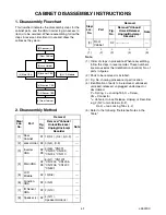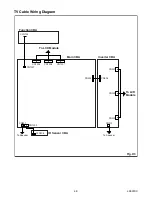
5-3
L2601EA
The following adjustment normally are not
attempted in the field. Only when replacing the
LCD Panel then adjust as a preparation.
3. White Balance Adjustment
Purpose:
To mix red, green and blue beams correctly
for pure white.
Symptom of Misadjustment:
White becomes bluish
or reddish.
Note:
Use service remote control unit
1. Operate the unit for more than 20 minutes.
2. Input the White Purity (APL 80% or APL 20%).
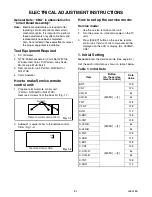
3. Set the color analyzer to the CHROMA mode and
bring the optical receptor to the center on the
LCD-Panel surface after zero point calibration as
shown above.
Note:
The optical receptor must be set
perpendicularly to the LCD Panel surface.
4.
[RF/VIDEO1]
Enter the Service mode. Press “VOL
p
” button on
the remote control unit and select “C/D-1” mode.
[VIDEO2]
Enter the Service mode. Press “VOL
p
” button on
the remote control unit and select “C/D-2” mode.
5.
[RF/VIDEO1]
When “x” value and “y” value are not within
specification, adjust “DB (C/D1)” or “DR (C/D1)”.
Refer to “1. Initial Setting.”
Note:
“DB(C/D1)” or “DR(C/D1)” must be adjusted
within ±0.01.
[VIDEO2]
When “x” value and “y” value are not within
specification, adjust “DB(C/D2)” or “DR(C/D2)”.
Refer to “1. Initial Setting.”
Note:
“DB(C/D2)” or “DR(C/D2)” must be adjusted
within ±0.01.
6. Turn the power off and on again. (Main power
button on the TV unit.)
Test Point Adj. Point
Mode
Input
Screen
VOL.
p
buttons
[RF/VIDEO1]
C/D1
[VIDEO2]
C/D2
White Purity
(APL 80%)
or
(APL 20%)
M. EQ.
Spec.
Pattern Generator,
Color analyzer
x: 0.271 to 0.281,
y: 0.277 to 0.287
Figure
Color Analyzer
It carries out in a darkroom.
L = 3 cm
Perpendicularity
INPUT: WHITE 80%
Summary of Contents for EWL20S5
Page 27: ...8 3 Main 1 5 Schematic Diagram L2601SCM1 ...
Page 28: ...8 4 L2601SCM2 Main 2 5 Schematic Diagram ...
Page 29: ...8 5 Main 3 5 Schematic Diagram L2601SCM3 ...
Page 30: ...8 6 L2601SCM4 Main 4 5 Schematic Diagram ...
Page 32: ...8 8 L2601SCF Function Schematic Diagram ...
Page 33: ...8 9 L2601SCIR IR Sensor Schematic Diagram ...
Page 34: ...8 10 L2601SCI Inverter Schematic Diagram ...
Page 38: ...8 14 Inverter CBA Top View BL2500F01021 Inverter CBA Bottom View ...
Page 52: ...EWL20S5 L2601UB 2006 05 29 ...


