3
EN-DFA Series
North America
Only
The EN-DFA Series is designed with flanged connections,
and the arrestor provides the option of the removal of the
flame cell element for easy cleaning and replacement
without disconnecting of the pipe connection.
Principle of Operation
Detonation flame arrestor prevents flame propagation
as it enters the exposed side of the unit to the
protected side by absorbing and dissipating heat
using spiral wound crimped ribbon flame cells.
This detonation flame arrestor utilizes a patented
element assembly that dampens the high velocities
and pressures associated with deflagrations and
detonations while quenching the flame front. These
cells allow maximum flow with maximum protection.
Detonation flame arrestor has the heat capacity
and structural design to withstand all the dynamic
conditions of flame propagation and still stop the
flame. Detonation flame arrestor is used when the
flame can be in any of the detonation states.
Limits for Use
The operational temperature, T
0
, shall be limited
as follows:
-4°F ≤ T
0
≤ 140°F / -20°C ≤ T
0
≤ 60°C
The operation pressure, p
0
, shall be limited as follows:
See Table 5
Flame arrestor use shall be limited to gas-air mixtures
with an Maximum Experimental Safe Gap (MESG)
equal to or greater than that tested.
Additional Protection Measures: Flame arrestors
may be used with additional protection measures.
The overall safety of the combined installation shall
be accessed, taking account of any hazardous area
classification (zones) and the likelihood of additional
ignition sources.
Factors Affecting Flame
Arrestor Performance
Gas Group
The type of gas in the system determines its gas
grouping and therefore predetermines the type of
arrestor element required. The element must be
designed to accommodate the specific gas group that
could possibly ignite and propagate in the system.
The more explosive gases require the flame cell to
absorb the heat more quickly and efficiently. The
International Electrotechnical Commission (IEC)
groups gases and vapors into Groups IIA through IIC
categories depending on a number of factors including
the MESG of the gas.
Figure 3.
EN-DFA Series Detonation Flame Arrestor Available Constructions and Model Numbering System
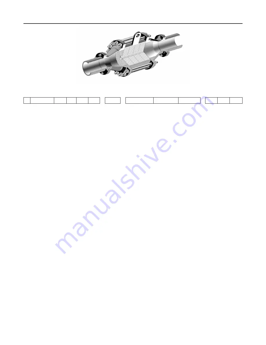
Figure 2.
Cut-away view of EN-DFA Series Detonation Flame Arrestor
EN
DFA
/
-
-
Detonation
Flame
Arrestor
Housing
Size
Connection
Size
IEC
Gas
Group
Housing
Material
Element
Material
Connection
Type
Options
(Concentric)
04 = 4 in.
through
26 = 26 in.
02 = 2 in.
through
12 = 12 in.
IIA (D)
IIB3 (C)
C = Carbon Steel
4 = 304 SST
6 = 316 SST
H = Hastelloy
®
4 = 304 SST
6 = 316 SST
H = Hastelloy
®
F = Flat face
flange
R = Raised
face
flange
1 = Drain Plug
2 = Pressure Tap
3 = Temperature Probe
Tap
(standard)
4 = Miscellaneous
5 = Protective coating
6 = Special feature
Hastelloy
®
C is a mark owned by Haynes International, Inc.


