


Installation, Operation and Maintenance Manual
VCIOM-15204-EN Rev. 1
May 2020
3
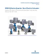
Section 3: External Construction
Figure 1
HQ-008 – HQ-120
Figure 2
HQ-200 – HQ-300
Conduit Entries
MDPI
Cover Bolts
Drive Bushing
Declutch
Lever
Cover
Handwheel
Travel Stop Bolts
Drive Bushing
Travel Stop Bolts
Gearbox
MDPI
Section 3: External Construction
External Construction