background image

26

 • 

E2 RX/BX/CX I&O Manual 

026-1621 Rev 0 12-JUN-2012

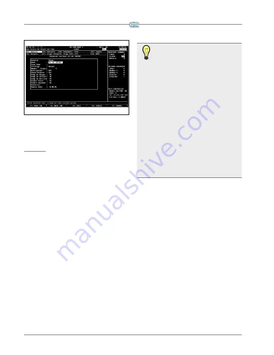
3.11.2.3 Navigating the Setup Screen

Figure 3-35

 - Typical Setup Screen (RX version shown)

The Setup utility is the interface used to change set-

tings and setpoints, and define inputs and outputs in the 
E2. 

Figure 2-8

 and 

Figure 3-35

 show a typical Setup 

screen and its primary elements.

Index Tabs

The ten boxes at the top of the screen labeled 

C1


through 

C0

 are known as the 

index tabs

. These tabs pro-

vide a short index of the screens that are used to set up the 
current application. The numbers 

C1

 through 

C0

 represent 

the screen numbers (

C1

 being screen 1, 

C2

 being screen 2, 

and so on).

Each of the Setup screens that you may access will 

have a name beside its number. But as in 

Figure 2-8

 and 

Figure 3-35

 for example, you will notice some tabs have 

names, while others are blank.

As you move through these screens within the Setup 

Editor, the highlight will move to different tabs to indicate 
which screen is being displayed.

• Pressing 

 (PREV TAB) will back-up the order 

of the screens.

•   Pressing 

 (HOME) at any point will take you 

to the Main Status (Home) screen.

TIP: To see each screen in a typical setup for 
the E2 RX controller, start from the Main Sta-
tus (Home) screen.

1.

Position the cursor somewhere inside the Suc-

tion Groups section and press 

 and 


(Setup), or just


 (SETUP) from the Home 

screen. The General Setup screen will be dis-
played.

2.

Press 

 (NEXT TAB) to move the cursor 

to Setpoints. The Setpoints Setup screen is dis-
played.

3.

Press 

 again and the Inputs Setup screen 

comes up.

4.

Press 

 a few more times to see the rest of 

the Setup menu screens. When the C0 tab 
(MORE) is highlighted, there may be more 

than one extra Setup screen. Press 


(zero) to see a list of all Setup screens for that 
application.

5.

Keep pressing 

 while taking note of the 

extra screens until C1 is highlighted once 
more.

These screens (

C1

 through 

C0

) contain all of the set up 

information that is associated with the selected suction 
group.

Blank tabs are inaccessible. There are several reasons 

why a tab may be inaccessible (i.e., without a name next to 
the number):

• The tab (and the corresponding screen) is unused 

and reserved for later revisions.

• The screen may only be accessed when running in 

Full Options mode.

• The screen may require one or more fields to be set 

to certain values before the screen may be accessed. 
For example, a screen containing nothing but com-
pressor proof input definitions might be hidden if 
there is a field on another screen that tells the sys-
tem there are no proof checking devices on the 
group’s compressors. To access this screen, you 
would have to set this field to “YES”. 

The screen you are currently in is always highlighted 

in the screen’s index tab. For example, in 

Figure 2-8

 and 

Figure 3-35

because Screen 1 is displayed, tab 

C1

 is 

highlighted. 

Summary of Contents for E2 BX Series

Page 1: ...026 1621 Rev 0 12 JUN 2012 Quick Start Guide for E2 RX Refrigeration BX HVAC and CX Convenience Store Controllers Applicable to E2 firmware versions 4 0 and above ...

Page 2: ......

Page 3: ...nce received including interference that may cause undesired operation CE COMPLIANCE NOTICE Class A Product Information for E2 Controllers The Retail Solutions Einstein and E2 controllers are Class A products In a domestic environment this product may cause radio interference in which case the user may be required to take adequate measures This covers All E2 family product types RX Refrigeration C...

Page 4: ......

Page 5: ...enu 7 3 SETUP 8 3 1 SET UP TIME DATE 8 3 1 1 Setting the Time and Date 9 3 2 SET UP MODEM 10 3 3 SET UP TCP IP 10 3 4 SET UP NETWORK BAUD RATES 11 3 4 1 COM1 Serial RS232 Baud Rate 11 3 4 2 I O Network Baud Rate 12 3 5 SET UP USER ACCESS 12 3 5 1 Changing Required User Access Levels 13 3 5 2 Creating a New User Account 13 3 5 3 Deleting a User 14 3 6 SET UP I O NETWORK 14 3 6 1 Specify Number of B...

Page 6: ... 9 4 Introduction Alarm Reporting 22 3 10 SET UP GLOBAL DATA 22 3 10 1 Priority Settings 23 3 11 SET UP APPLICATIONS 24 3 11 1 Add Delete an Application 24 3 11 2 Using and Configuring a Setup Screen 25 3 11 2 1 The Edit Menu 25 3 11 2 2 Entering Setpoints 25 3 11 2 3 Navigating the Setup Screen 26 3 11 3 Using the Help Key to Get Property Help 27 APPENDIX A TROUBLESHOOTING A 1 ...

Page 7: ...l There are two buttons located midway down on the main board These buttons are used to perform various hardware functions For more information about E2 hardware refer to the E2 manual P N 026 1614 Reset Button The button labeled RESET on the main board resets the controller Press ing and holding this button for one second will cause the E2 to reset and retain all programmed applica tions logs and...

Page 8: ...Os relay output boards on this E2 s I O Network 8DO Boards Enter the number of 8DO digital out put boards on this E2 s I O Network 4AO Boards Enter the number of 4AOs MultiFlex 168AOs and MultiFlex 88AO analog output boards on this E2 s I O Network IRLDS Controllers Enter the number of IRLDS RLDS leak detection units on this E2 s I O Network Unit Controllers Echelon Liquid Ctrls CC100P CC100LS Ent...

Page 9: ...me screen for the E2 When no one is logged in to the controller this is the screen that will be shown in the display When a user is logged into the controller the Home screen is displayed when the user is not performing any actions such as appli cation setup viewing other status screens etc The Home screen will vary depending on the configu ration of the controller In most cases the Home screen wi...

Page 10: ...ers are logged in Terminal mode in use E2 is connected to Ethernet Wait or system is busy Disk activity or saving to disk Caps lock is ON 2 2 2 The Function Keys Figure 2 4 Home Screen Function Keys RX version shown At the very bottom of every screen in the E2 there are five boxes labeled through These boxes are the function key descriptions The function key descrip tions show what each of the fiv...

Page 11: ... overrides are active Each status screen is specially designed to provide a concise at a glance view of how one or more systems are functioning TIP To view the Suction Group Status screen in the RX controller start from the Home screen Press the function key SUC TION GRP If more than one Suction Group has been set up the Suction Group Summary screen opens Choose which application you wish to view ...

Page 12: ...Opens the Circuit Bypass screen to force a manual or emergency defrost or wash mode Application Commands Allows Service Start End for Irriga tion and Pulse Accumulation applica tions Applications Logs Graphs Opens various log and graph screens for Anti sweat and Pulse Accumula tion applications Opens the Circuit Report screen for standard circuits only One of the more important features of the Act...

Page 13: ...t up dial outs and alarm reporting for the current E2 6 Logging Setup Enter information about Log ging Group applications such as the sampling frequency and total number of samples 7 Network Setup Opens the Network Setup menu where options to view network status add or delete boards and controllers commission devices set up a router and make board associations are available 8 Global Data Configure...

Page 14: ...echnician to make notes about changes made or general information 7 Display Users Enter information about Log ging Group applications such as the sampling frequency and total number of samples 8 Toggle Full Options When set to on FULL will appear at the top right of the screen and gives user full access to options and applica tions 9 Application Default Value Setup Choose the default values most a...

Page 15: ...E2 time is off by 5 seconds or greater the SNTP will update the E2 time if enabled When the E2 time is updated an entry in Service Log is added If this field is set to No the E2 clock will have to be set manually If this field is set to Yes SNTP support is used Two SNTP servers are supported Primary Time Server and an optional Secondary Time Server Primary Time Server The E2 will call up this prim...

Page 16: ...lly connects to the Sundown out put 3 2 Set Up Modem Figure 3 3 Modem Select Screen From the Main Menu 1 Press System Configuration 2 Press Remote Communications 3 Press Modem Setup to advance to the Gen eral Services screen You can choose between an internal modem one that is mounted directly on to the E2 circuit board via the PC 104 slot in previous generation E2 circuit boards or an external mo...

Page 17: ...that assigns a dynamic IP address to devices on a network With dynamic addressing a device could have a different IP address every time it connects to the network When set to Yes DHCP Enabled keeps track of IP addresses and enables a new IP device to be added to a network without having to manually assign it a unique IP address DHCP supports a mix of static and dynamic IP addresses 3 4 Set Up Netw...

Page 18: ...creen from the System Information menu 1 Press to open the Main Menu 2 Press System Configuration 3 Press System Information Figure 3 7 System Information Menu In the User Access Setup screen you may add user names and passwords to the controller with varying levels of security and customize user access for each security level To access this menu choose option Passwords User Access from the System...

Page 19: ...tc Each row has five columns each of which corresponds to a different category of user actions Setpoint This includes all actions that change application setpoints Also clearing one or more alarms out of the Alarm Advisory Log is considered a setpoint action refer to the Operator s Guide to Using the E2 section of the E2 manual P N 026 1614 for the definition of clearing alarms Bypass This include...

Page 20: ...k Setup The Network Setup menu displays four options Network Summary Connected I O Boards Controllers Router Setup Controller Associations For the total E2 devices online or offline status setup screens changing board or controller names config uring and commissioning devices deleting a device and viewing detailed status screens of controllers select Net work Summary For the number of I O Network ...

Page 21: ...screens of controllers After determining if a board is offline turn to Appen dix A Troubleshooting 3 7 Set Up Echelon Network 3 7 1 Specifying Number of Devices To specify the number of devices on the Echelon Net work navigate to the Connected I O screen 1 Press to open the Main Menu 2 Press System Configuration 3 Press Network Setup 4 Press Connected I O Boards Controllers Figure 3 12 Connected I...

Page 22: ...Press to open the Main Menu 2 Press System Configuration 3 Press Network Setup 4 Press Network Summary Figure 3 13 Network Summary Screen How Echelon Commissioning Works Each device that is capable of communicating on a Echelon Network has a unique 12 digit Neuron ID code number that is hard coded in a chip on the board In order for the E2 to begin communications with a unit controller or another ...

Page 23: ...All that is left to do is to press the service button on the device to be commissioned CAUTION When the E2 s Wait Time dura tion begins the E2 will accept the first Neuron ID code it receives Be sure that no other ser vice buttons on any devices on the network are being pressed during the Wait Time Since the service button on the CC 100 is its Hand held Terminal jack be sure that no one has a Hand...

Page 24: ...e on the list is installed and locate each device s Neuron ID sticker Every Echelon compatible device available from Retail Solutions has a sticker on its enclosure that shows the unit s Neu ron ID number Each sticker also has a perforated tag at the bottom that may be removed and affixed to your form Tear this tag off and stick it in the Neuron ID blank on the sheet of paper If the perforated tag...

Page 25: ...s on that E2 the current number and maximum number of each of those applications allowed and which additional features that require a license key have been enabled From the Main Menu 1 Press System Configuration 2 Press Licensing 3 Press Add Feature Enter your license key to activate the desired feature Figure 3 21 Enter Your Unique License Key 4 Reboot the controller and open the License Report s...

Page 26: ... 3 9 1 2 The Alarm Output Each E2 has a single digital output that reacts to alarm reports An alarm can be reported to this output in which case the output turns ON and remains on until the alarm condition has returned to normal 3 9 1 3 Dial Out Alarms may be sent to remote alarm receivers via the modem defined for the controller Possible dial out devices include a PC running UltraSite a printer a...

Page 27: ...r the AnnuncIsHomesScrn property becomes available in General Services to select if the Annunciator log is to be the Home screen The property will default to Yes If the property is set to No the Home screen will be either the default Home screen or the user selected Home screen Figure 3 26 Alarm Annunciator 3 9 3 Alarm Dial Out Figure 3 27 Alarm Setup Menu One of the E2 s most important alarm repo...

Page 28: ... The Alarm Annunciator If multiple E2s exist on a network you may choose to send alarms across the LonWorks Network so that they may be picked up by the Alarm Annunciator Refer to Section 3 9 2 for information on how an Alarm Annunciator works 3 10 Set Up Global Data Figure 3 30 System Configuration Menu In a network with multiple E2s it is often the case that certain sensors or transducer values ...

Page 29: ...he secondary provider will assume the primary sensor has failed and it will send the secondary value to all other Global Data applications on the net work These applications will then use the secondary value in place of the failed primary value Secondary providers will continue to send the input value until the primary provider again sends a valid update to the other Global Data applications The s...

Page 30: ...ed with applications 3 11 Set Up Applications From the Main Status Home screen place the cursor on the application you wish to view and press SETUP You can also press and select Setup from the Actions Menu to open the Setup screen for your selected application 3 11 1 Add Delete an Application Add an Application 1 Press the key to open the Main Menu screen 2 Select Add Delete Application to open th...

Page 31: ...oller Logging Setup enables the user to turn logging on for a particular parameter Note that if L appears next to the parameter default logging has already been enabled for the Logging Group Cell Bypass Setup Opens screen for bypass input types which are Momentary or Level triggered and remain active for a Bypass Duration For example Time Schedules have two such inputs I O Mode toggles between dis...

Page 32: ...and Setup or just SETUP from the Home screen The General Setup screen will be dis played 2 Press NEXT TAB to move the cursor to Setpoints The Setpoints Setup screen is dis played 3 Press again and the Inputs Setup screen comes up 4 Press a few more times to see the rest of the Setup menu screens When the C0 tab MORE is highlighted there may be more than one extra Setup screen Press zero to see a l...

Page 33: ...eys for Setup Screens Key Function Description PREV TAB Moves backward one screen NEXT TAB Moves forward one screen EDIT Opens the Edit Menu box STATUS OVER RIDE or LOOKUP Opens the Detailed Sta tus screen Opens the Override Update screen or Look Up Tables CANCEL Cancels the operation After all of the functions of E2 are set up the next step is to set the System Configuration which is basically ho...

Page 34: ......

Page 35: ... network dip switches Verify net work ID number is not a duplicate and that baud rate switches are set to 9600 If switches are wrong make changes and then reset the controller Terminating resistance jump ers are set incorrectly Check for proper setting of terminating resistance jumpers Network segment should be terminated on the two endpoints of the daisy chain and untermi nated everywhere else Bo...

Page 36: ...pressors were assigned the proper rating HP AMP or BTU Pressure setpoints are set up incorrectly Set proper pressure setpoints If you are controlling the rack using suction pres sure enter the pressure setpoint in the SUC PRES SETPT field If you are controlling by temperature enter the temperature setpoint in the CTRL TEMP SETPT field Note Pressure setpoints are located under the Set points tab C2...

Page 37: ...2 From the Status menu press 4 for the Graphs Logs menu 3 Press 3 for the Override Bypass Log This screen gives you quick access to all overrides bypasses in the system Rack is in Phase Fail Verify correct phase and verify correct input for phase loss If you specified that phase protection would be used on this rack the Phase Loss input is displayed The Phase Loss input is automatically configured...

Page 38: ...point is set too low Unsplit setpoint value is compared with discharge pressure value instead of temperature Enter the value in terms of discharge pressure Go to the Setpoints tab C2 in the Condensers Setup screen and check that the UNSPLIT STPT field value has been entered as a pressure value Half of the fans are not run ning Check the split fan relay output 1 Go to the Other Outs tab C7 in the C...

Page 39: ...a 5 volt powered 200PSI pressure transducer and Temperature is the standard Retail Solutions tem perature sensor NOTE The previous Eclipse and Standard sensors are now 5V and 12V respectively 2 From the Main Menu select System Configura tion 7 and Input Definitions 1 3 Highlight the desired input and press SETUP to check Sensor Type No Heat or Air Will Come On Incorrect board and points assignment...

Page 40: ...d press SETUP Move the cursor to C7 Inputs and high light the Board field Press LOOK UP choose the input device and press Highlight the Point field and press LOOK UP Select the type of schedule and press Make sure Lighting Control output is assigned Lights Will Not Come On With The Photocell Photocell is not recognized by controller Make sure the photocell is configured as an analog input Verify t...

Page 41: ......

Page 42: ...d or its affiliates collectively Emerson reserves the right to modify the designs or specifications of such products at any time without notice Emerson does not assume responsibility for the selection use or maintenance of any product Responsibility for proper selection use and maintenance of any product remains solely with the purchaser and end user 026 1621 12 JUN 2012 Emerson is a trademark of ...

Reviews: