
1-5-1
E5900DC
CABINET DISASSEMBLY INSTRUCTIONS
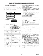
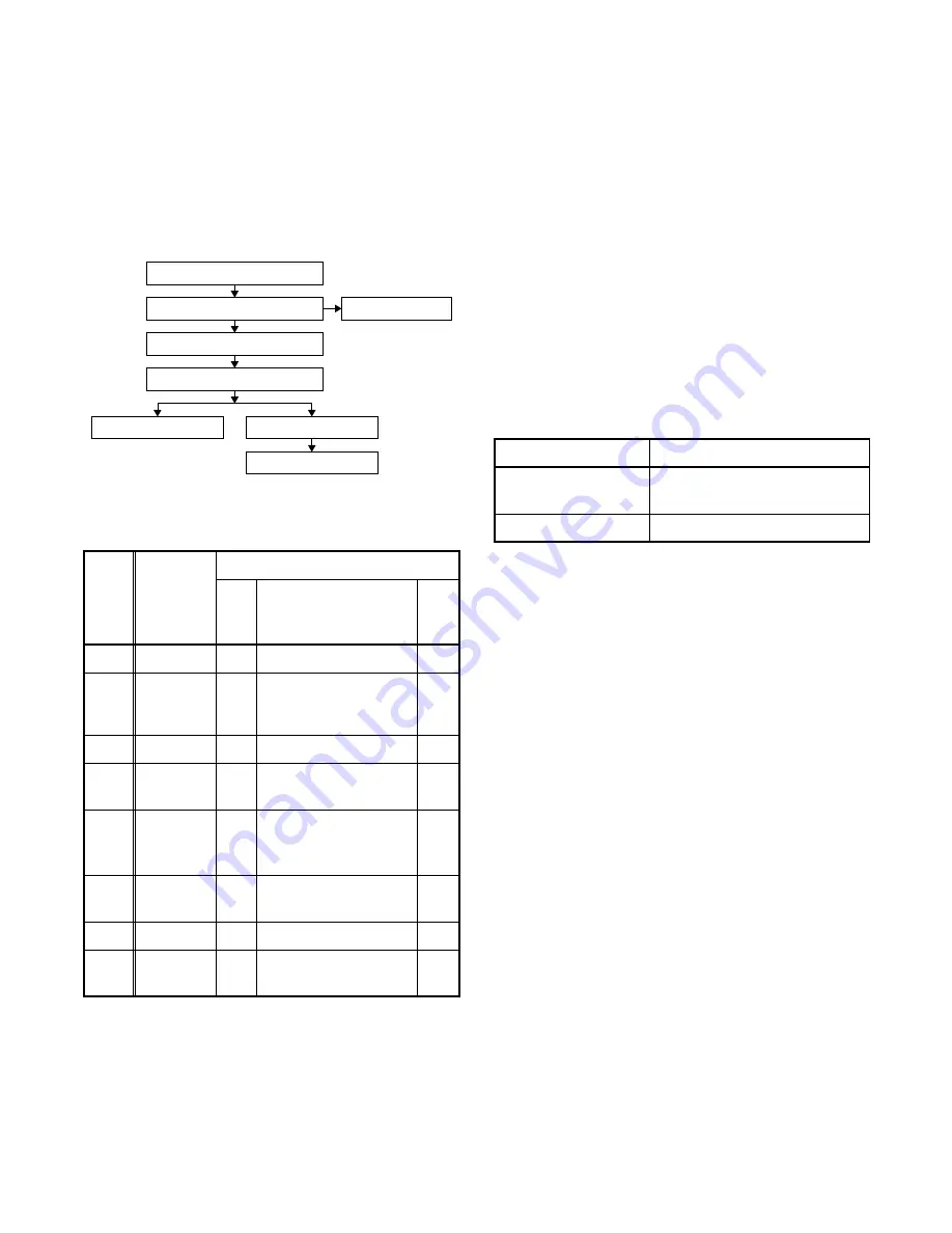
1. Disassembly Flowchart
This flowchart indicates the disassembly steps to gain
access to item(s) to be serviced. When reassembling,
follow the steps in reverse order. Bend, route, and
dress the cables as they were originally.
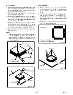
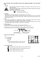
2. Disassembly Method
(1): Identification (location) No. of parts in the figures
(2): Name of the part
(3): Figure Number for reference
(4): Identification of parts to be removed, unhooked,
unlocked, released, unplugged, unclamped, or
desoldered.
P=Spring, L=Locking Tab, S=Screw,
CN=Connector
*=Unhook, Unlock, Release, Unplug, or Desolder
e.g. 2(S-2) = two Screws (S-2),
2(L-2) = two Locking Tabs (L-2)
(5): Refer to “Reference Notes.”
About tightening screws
When tightening screws, tighten them with the follow-
ing torque.
Reference Notes
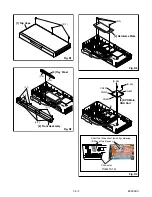
CAUTION 1: Locking Tabs (L-1), (L-2), (L-3) and (L-4)
are fragile. Be careful not to break them.
1-1. Release four Locking Tabs (L-1). Then, release
three Locking Tabs (L-2).
1-2. Release three Locking Tabs (L-3). Then remove
the Front Assembly.
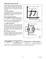
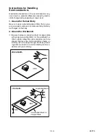
CAUTION 2: Electrostatic breakdown of the laser
diode in the optical system block may occur as a
potential difference caused by electrostatic charge
accumulated on cloth, human body etc, during
unpacking or repair work.
To avoid damage of pickup follow next procedures.
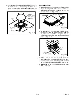
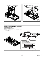
2-1. Short the three short lands of FPC cable with sol-
der before removing the FFC cable (CN201) from
it. If you disconnect the FFC cable (CN201), the
laser diode of pickup will be destroyed. (Fig. D4)
2-2. Disconnect Connectors (CN301), (CN401) and
(CN601). Remove two Screws (S-3A) and (S-3B)
and lift the DVD Main CBA Unit. (Fig. D4)
CAUTION 3: When reassembling, confirm the FFC
cable (CN201) is connected completely. Then remove
the solder from the three short lands of FPC cable.
(Fig. D4)
ID/
LOC.
No.
PART
REMOVAL
Fig.
No.
REMOVE/*UNHOOK/
UNLOCK/RELEASE/
UNPLUG/DESOLDER
Note
[1]
Top Case
D1
3(S-1)
-
[2]
Front
Assembly
D2
*4(L-1), *3(L-2),
*3(L-3)
1
1-1
1-2
[3]
Tray Panel D2
*2(L-4)
1
[4]
Reinforce
Plate
D3
3(S-2)
-
[5]
DVD Main
CBA Unit
D4
(S-3A), (S-3B)
*CN201, *CN301,
*CN401, *CN601
2
2-1
2-2
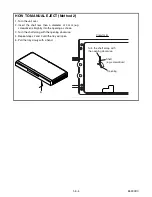
[6]
DVD
Mecha
D4,
D5
4(S-4)
2
3
[7]
AV CBA
D6
(S-5), 4(S-6), *2(L-5)
-
[8]
Function
CBA
D6
*CN2001
-
↓
(1)
↓
(2)
↓
(3)
↓
(4)
↓
(5)
[1] Top Case
[2] Front Assembly
[4] Reinforce Plate
[5] DVD Main CBA Unit
[6] DVD Mecha
[7] AV CBA
[3] Tray Panel
[8] Function CBA
Screws
Torque
(S-1), (S-2), (S-3A),
(S-4), (S-5), (S-6)
0.45 ± 0.05 N·m
(S-3B)
0.38 ± 0.04 N·m
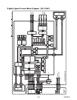
Summary of Contents for DVL100E
Page 1: ...SERVICE MANUAL DVD PLAYER EWD7004 DVL700E DVL100E ...
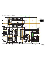
Page 32: ...1 7 23 BE5900F01012B 1 7 24 FUNCTION CBA Top View FUNCTION CBA Bottom View ...
Page 41: ...1 14 2 E5900EX Packing A22 S1 S2 S4 Unit X10 X5 X2 X4 S2 X1 ...
Page 48: ...EWD7004 DVL100E DVL700E E5900UD E5922UD E5925UD 2004 03 01 ...