D7.8.4/0112-0415/E
14/17
6
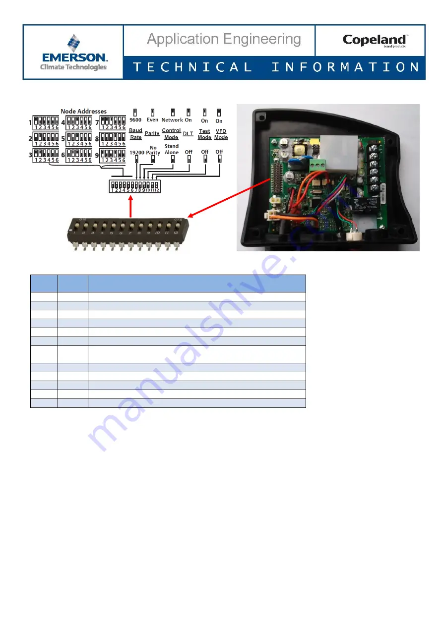
CoreSense Diagnostics DIP-switch settings
Figure 17: CoreSense Diagnostics DIP-switch
DIP-
switch
Factory
setting
DIP-switch function
1
On
Node address for communication
2
Off
Node address for communication
3
Off
Node address for communication
4
Off
Node address for communication
5
Off
Node address for communication
6
Off
Node address for communication
7
Off
Communications Baud rate
Off: 19200 Baud
On: 9600 Baud
8
Off
Off: No parity
On: Even parity
9
Off
Off: Stand-alone mode
On: Network mode
10
On
On: DLT enabled
Off: DLT disabled
11
TBD
Self-test function for oil functionality
12
Off
On: VFD application
Off: Non VFD application
Table 5: CoreSense Diagnostics DIP-switch setting
If you use CoreSense communication, assign a unique node address to each CoreSense Diagnostics module using
switches 1 through 6.
a. Set the communications
baud rate for the module using switch 7. “Off” = 19200 baud, “On” = 9600 baud.
The baud rate for each module should be set to match the pack controller.
b.
Set switch 8 to “Off” for no parity, to “On” for even parity.
c.
Set switch 9 to “Off” for stand-alone mode, to “On” for network mode. Network mode will generate a
communications error if the pack controller fails to communicate with the device. For stand-alone mode, no
communications are expected so the communication error is blocked.
d. Factory default setting is
“On” for DIP-switch 10, ie, discharge temperature protection. If you want to
disconnect the discharge temperature sensor, turn off DIP-switch 10.
Push the reset button after changing the switch settings.
Ensure that the DIP-switch settings on each module match the settings for the selected controller communication
port.


