


8
C6.3.2/0416-0716/E
In the case of high-powered motors the breakaway starting currents become so large that they
lead to disruptive voltage dips in the mains. The compressors that are subject to current
limitation must therefore by all means be equipped with starting load reduction to guarantee
perfect starting even when the voltages amount to less than approximately 85% of the voltage
on the nameplate.
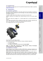
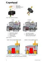
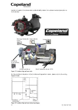
2.6.8 Oil pumps
The oil pumps used for Stream Digital compressors are independent of their rotating direction.
In compressors delivered with CoreSense
™ Diagnostics (-D), the oil pump integrates the
electronic switch for integrating oil pressure safety functionality.
Compressors delivered with CoreSense
™ Protection (-P) are designed to accommodate fittings
for an OPS2 (oil sensor included in the oil pump). A mechanical oil safety device like the Alco
Control FD-113ZU can also be used.
2.6.9 Oil pressure
Normal oil pressure is between 1.05 and 4.2 bar higher than crankcase pressure. Net oil
pressure can be read by connecting two pressure gauges to the compressor and comparing the
readings. One gauge should be connected to the oil pump. The second gauge should be
connected to the crankcase (T-fitting instead of plug on the compressor crankcase) or the
suction service valve.
During irregular operating conditions, eg, a blockage of the suction filter, the pressure measured
at the suction shut-off valve of the compressor may differ widely from that measured at the
crankcase. Therefore pressure drops have to be avoided.
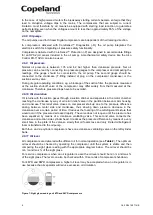
2.6.10 Oil circulation
Oil returns with the suction gases through a suction strainer and separates in the motor chamber
reaching the crankcase by way of oil return relief valve in the partition between motor housing
and crankcase. This relief valve closes on compressor start-up due to the pressure difference
arising between motor side and crankcase, thus slowing down pressure decrease in the
crankcase over a certain period of time. It reduces the foaming of the oil/refrigerant mixture that
would occur if the pressure decreased rapidly. The valve does not reopen until the pressure has
been equalized by means of a crankcase ventilating valve. This second valve connects the
crankcase and suction side cylinder head. It reduces the pressure difference by means of a very
small bore in the plate of the valve so slowly that oil foams less and only limited oil/refrigerant
foam is transferred to the oil pump.
Both four- and six-cylinder compressors have one crankcase ventilating valve on the left cylinder
bank.
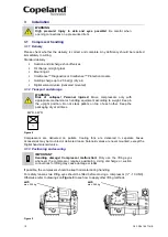
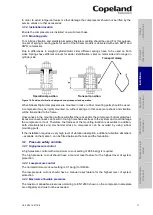
2.6.11 Oil level
All compressors are delivered with sufficient oil for normal operation (see
Table 2
). The optimum
oil level should be checked by operating the compressor until the system is stable and then
comparing the sight glass reading with the appropriate diagram below. The oil level should be
min ¼ and max ¾ of the sight glass.
For service compressors when an oil regulator is used the oil level should be min ¼ and max ¾
of the sight glass. The level can also be checked within 10 seconds of compressor shut-down.
For 4M*D and 6M*D compressors a higher oil level may be accepted when an oil regulator is in
use because the oil separator will reduce excessive oil circulation.
Figure 7: Sight glass reading on 4M*D and 6M*D compressors


