C6.2.7/1007-0619/E
15
4.4 Pressure safety controls
4.4.1 High-pressure protection
The cut-out setting for the high-pressure control shall be determined according to regional standards,
usually EN 378, part 2 in Europe.
The maximum pressure value for the individual compressor type, PS high side, is printed on the
nameplate of the compressor.
The high-pressure cut-out should have a manual reset feature for the highest level of system
protection.
4.4.2 Low-pressure protection
IMPORTANT
Loss of system charge and lubrication! Bearing malfunction!
Compressor breakdown!
A low-pressure control is highly recommended. Do
not bridge or by-pass the low-pressure cut out.
The minimum cut-out setting shall be determined according to the refrigerant and to the allowed
operation envelope
– see technical data in Select software at
. For
example, a minimum cut-out setting of 1.0 bar(g) is required for ZRH* and ZBH* compressors using
R407C.
The low-pressure cut-out should have a manual reset feature for the highest level of system
protection.
4.4.3 Internal pressure relief valve
ZRH(V)* and ZBH(V)* horizontal compressors do NOT have any internal pressure relief valve. To
ensure safe operation, a high-pressure control must be used in all applications.
4.5 Discharge gas temperature protection
IMPORTANT
Inadequate lubrication! Scroll set damage!
All ZRH* and ZBH* horizontal
Scroll compressors must be equipped with an external discharge gas
temperature protection.
Internal discharge temperatures can reach unacceptable values under some extreme operating
conditions (such as loss of refrigerant injection charge or extremely high compression ratio). This
could cause compressor damage.
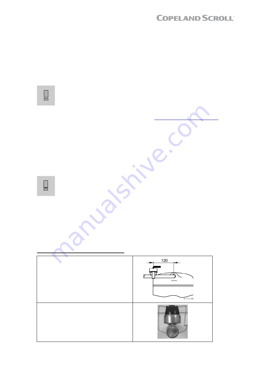
The discharge thermostat dedicated to ZRH* and ZBH* horizontal Scroll compressors has a cut-out
setting of 105°C ± 4K with closing at 88°C ± 8K. It should be installed approximately 120 mm from
the discharge valve outlet (see assembly instructions below).
To ensure proper functioning and to avoid false readings, the discharge line thermostat must be
installed and insulated according to the procedure and recommendations hereunder.
Assembly of the discharge line thermostat
▪
Install the discharge line thermostat on the
discharge tube 120 mm from top cap.
▪
Snap the retainer clip over the tube and onto
the thermostat.
▪
The thermostat should be placed on the
discharge tube so that its body is in upward
position on a horizontal tube installation.
▪
Ensure that the thermostat is not tilted.


