AE4-1322
© 2002 Copeland Corporation
Issued 4-2002
Printed in U.S.A.
11
3.5 Additional cooling by means of external oil
3.5 Additional cooling by means of external oil
3.5 Additional cooling by means of external oil
3.5 Additional cooling by means of external oil
3.5 Additional cooling by means of external oil
cooler
cooler
cooler
cooler
cooler
The application of an external oil cooler (air, water or
refrigerant cooled) instead of refrigerant inject provides
additional extension of the application envelopes and
even better efficiency.
When calculating an oil cooler, worst case operating
conditions must be used:
•
Min. evaporating temperature
•
Max. suction gas superheat
•
Max. condensing temperature
•
Operation mode (capacity control, ECO)
Oil cooler capacity can be calculated by using the
selection software.
Recommendations for external oil coolers
Recommendations for external oil coolers
Recommendations for external oil coolers
Recommendations for external oil coolers
Recommendations for external oil coolers
•
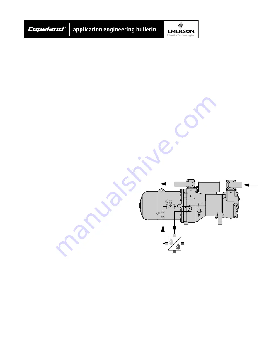
Connections for external oil coolers are located on
the back side of the compressor below the dis-
charge shut-off valve (oval or rectangular flange).
The flange is replaced by a tube adaptor (option):
•
Install oil cooler as close as possible to the com-
pressor.
•
Piping design must avoid gas pockets and any
drainage of oil into the compressor during shut-
downs (installation of the oil cooler preferably at
compressor level or below).
•
Due to the additional oil volume (cooler, piping) a
solenoid valve may be necessary in the oil line.
This is to avoid oil migration into the compressor
during shutdowns. The solenoid valve must be
installed close to the compressor’s oil inlet connec-
tion and its electric control should be parallel to the
contactor’s normally open contact. Recommended
additional components:
- Sight glass to check oil flow,
- Manual shut-off ball valves in both feed and
return lines for ease of service,
- Oil filter (max. 25 µ mesh size)
With an additional oil volume (cooler and piping) of
10% of the compressor’s standard oil charge and
assured cleanliness of components and pipes the
above mentioned measures can be omitted.
•
Oil coolers must be controlled by thermostats (see
table for temperature settings).
•
For rapid heating of the oil circuit and minimizing
the pressure drop with cold oil an oil by-pass (or
even heating the cooler during shut down) is
required under the following conditions:
-
the oil temperature in the cooler drops below
60°F during shut down,
-
the oil volume of cooler plus oil piping exceeds
the compressor’s oil charge,
-
The oil cooler is an integral part of the con-
denser coil
•
The by-pass valve should have a temperature
responsive modulating control function. The use of a
solenoid valve for intermittent control would require
highly sensitive control thermostat and a minimal
switching differential (effective temperature variation
< 18°F).
•
The oil side pressure drop during normal operation
should not exceed 7 psig.
Water cooled oil cooler
Water cooled oil cooler
Water cooled oil cooler
Water cooled oil cooler
Water cooled oil cooler
Temperature control by thermostatic water regulator
(for set point see table, required sensor temperature
should be equal to or greater than 250°F).
Figure 8
External oil cooler connection


