6
CLARKSON
KNIFE GATE VALVE MODEL ZP3OO
INSTALLATION AND MAINTENANCE INSTRUCTIONS
NOTES
1. Stop all small leaks as soon as possible as
considerable damage can be done to the valve
and the surrounding area if leakage is allowed to
continue.
2. Replacement parts including replacement liners,
hand wheel and yoke assemblies, gates, packing
glands, and packing can be provided from our
factory. If valve requires further repair, please
contact our office for an estimate of feasibility and
cost of repair.
REPACKING INSTRUCTIONS
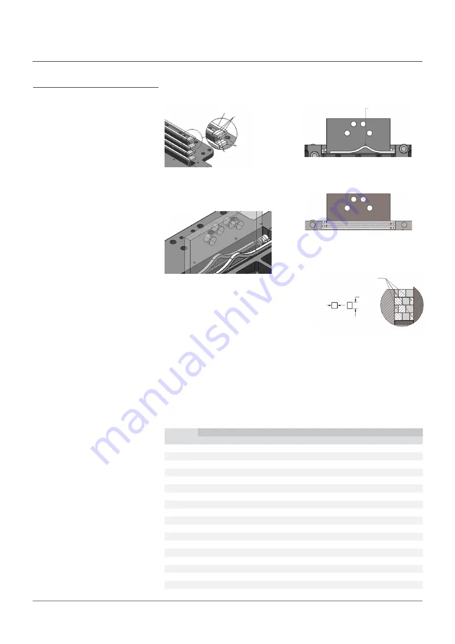
1. Each packing piece is cut a bit longer to add
some compression within each layer and to
accommodate for fraying strands of packing
at each end. The size, length, and quantity
of each piece can be found in the relevant
Table. Each layer shall alternate between
both the packing width pieces and the
position of the smaller end pieces, as shown
in Figure 12. Smaller end pieces will always
be the piece to deform into remaining cavity.
Note:
ensure body O-ring remains
protruding from packing box after
installation of packing.
2. Method of installing packing is shown in
Figure 13. Place one end of packing to side
of packing box. The other end should touch
other packing pieces once installation of
packing commences.
3. Start at the hump of each packing piece
and pack the packing with a packing tool,
as shown in Figure 14. Once the pieces are
together to form the first layer, prepacking
with a packing tool is required to fill in any
gaps that can or cannot be seen. Each layer
will require prepacking.
Note:
do not let packing pieces to twist
during installation.
4. Alternate packing layers, as shown in
Figures 12 and 15.
5. If packed properly, the smaller pieces
should fill in the cavity. Each layer of end
pieces should be stacked in a specific way
so that a piece of packing is sitting on top
of a split line from the previous layer, as
shown in Figure 16.To get the smaller
pieces to fill in the cavity, opposite sides
will have to be compressed to obtain an
elongated smaller piece.
Note:
not all sizes have smaller end pieces;
some will have equal size end pieces.
6. Install packing gland with studs, Bellville
Washers, and nuts as shown in Figure 17.
For initial tightening of packing gland,
tighten packing gland to achieve a
compression between 0.125-0.375”. Use
Loctite 262 (Red) on studs to secure in body.
Note:
ensure each stack is facing the
opposite direction and the final stack is
cupped downward before adding the nut.
7. Tension must be placed on the nut to
prevent the nut from backing out. First
stack starts on the bottom, cupped down on
the packing gland, as shown in Figure 18.
Stacking method is provided on Table 2
FIGURE 12
Installation of packing (ZP300-24 shown)
Packing width piece
Packing end piece
Alternating layers
Smaller end piece
FIGURE 13
Installation of packing (ZP300-24 shown)
FIGURE 14
Installation of packing (ZP300-24 shown)
Use packing tool for packing,
starting at the hump of each
piece of packing
FIGURE 15
Packing layers alternating (ZP300-24 shown)
Compress
Elongate
FIGURE 16
Alternating packing end pieces (ZP300-24 shown)
Smaller piece
TABLE 2 - BELLEVILLE WASHER STACK - Alternative method: regular heavy hex nut
Valve size
NPS
Stack
1st
2nd
3rd
4th
5th
6th
7th
8th
9th
3
2 Down
2 Up
1 Down
1 Up
1 Down
1 Up
1 Down
-
-
4
3 Down
3 Up
3 Down
1 Up
1 Down
1 Up
1 Down
1 Up
1 Down
6
5 Down
5 Up
5 Down
1 Up
1 Down
1 Up
1 Down
1 Up
1 Down
8
2 Down
2 Up
2 Down
1 Up
1 Down
1 Up
1 Down
-
-
10
3 Down
3 Up
3 Down
1 Up
1 Down
1 Up
1 Down
-
-
12
4 Down
4 Up
1 Down
1 Up
1 Down
1 Up
1 Down
-
-
14
3 Down
3 Up
1 Down
1 Up
1 Down
1 Up
1 Down
-
-
16
7 Down
7 Up
7 Down
7 Up
1 Down
1 Up
1 Down
1 Up
1 Down
18
7 Down
7 Up
7 Down
7 Up
1 Down
1 Up
1 Down
1 Up
1 Down
20
16 Down
16 Up
1 Down
1 Up
1 Down
1 Up
1 Down
-
-
24
6 Down
6 Up
1 Down
1 Up
1 Down
1 Up
1 Down
-
-
26
8 Down
8 Up
1 Down
1 Up
1 Down
1 Up
1 Down
-
-
28
8 Down
8 Up
8 Down
1 Up
1 Down
1 Up
1 Down
1 Up
1 Down
30
9 Down
9 Up
9 Down
1 Up
1 Down
1 Up
1 Down
-
-
32
8 Down
8 Up
1 Down
1 Up
1 Down
1 Up
1 Down
-
-
36
7 Down
7 Up
1 Down
1 Up
1 Down
1 Up
1 Down
-
-
42
5 Down
5 Up
1 Down
1 Up
1 Down
1 Up
1 Down
-
-
48
10 Down
10 Up
1 Down
1 Up
1 Down
1 Up
1 Down
-
-


