background image

Installation, Operation and Maintenance Manual

RGS011110-1 Rev. 0


September 2015

8

Section 4: Travel Adjustment

Travel Adjustment

4�4 

Inward Travel Adjustment

• 

Removal of both cylinders is required and multiple adjustments may be required 
- for this reason we recommend against attempting to adjust inward motion, 
preferring to achieve adjustment via bracket motion, followed by resetting the  
end cap travel screws.

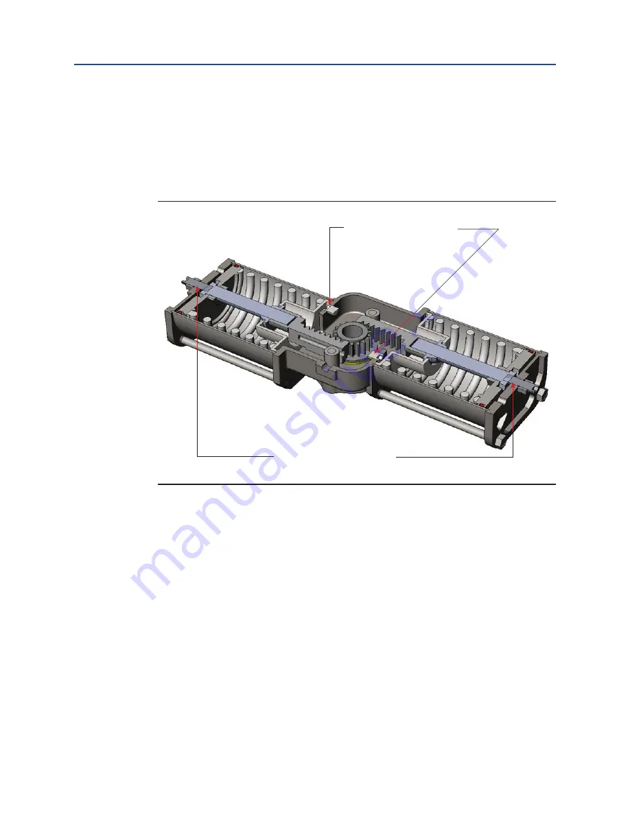
Figure 13 

Outward and Inward Travel Adjustment Screws

Inward Travel Adjustment Screws 

- One For Each Cylinder

Outward Travel Adjustment Screws 

- One For Each Cylinder

Summary of Contents for Bettis RGS Q Series

Page 1: ...Bettis RGS Q Series Stainless Steel Spring Return Actuators Single and Double Cylinder Types Installation Operation and Maintenance Manual RGS011110 1 Rev 0 September 2015 ...

Page 2: ......

Page 3: ...g 6 3 1 Single Cylinder Types Sizes 03 04 07 and 12 6 3 2 Double Cylinder Types Sizes 05 10 and 14 6 Section 4 Travel Adjustment 7 4 1 Single Cylinder Types Sizes 03 04 07 and 12 7 4 2 Double Cylinder Types Sizes 05 10 and 14 7 4 3 Outward Travel Adjustment 7 4 4 Inward Travel Adjustment 8 Section 5 Operation 9 Section 6 Maintenance 10 6 1 Piston Seal Replacement 10 6 2 Shaft Seal Replacement 15 ...

Page 4: ...ion less wear and longer life Other features result in there being fewer dynamic seals a seal that does not exist cannot fail Also we employ readily available off the shelf seals that cost far less than other s proprietary parts and we do so in a design that allows seal replacement while the actuator remains in line see Section 6 Maintenance Section Figure 1 Single Cylinder Models Bettis RGS Q Ser...

Page 5: ...anual RGS011110 1 Rev 0 September 2015 2 Section 1 Overview Overview Figure 3 Single Cylinder Model Section View Figure 4 Double Cylinder Model Section View NOTE Single and Double Cylinder models are identical except for the cylinder quantity ...

Page 6: ...lockwise rotation of the actuator shaft when pressure is exhausted from the end cap port ThebodyportonallBettisRGSQ Seriesspring returnactuatorsisforbreathingpurposes only Singleanddouble cylinderbodyportsmaybepressurizedtoaddtothespring forces butprovidesminimalbenefitanddefeatstherationaleforhavingaspring return AllBettisRGSQ Seriesactuatorshaveidenticaldrivegeometriesonbothfacesofthebody theref...

Page 7: ...terns directly in the body machining on both faces Figure 8 Sizes 03 04 and 05 Sizes 03 04 and 05 have body mounting surfaces even with the cylinder flanges allowing all size brackets to mount Sizes 07 10 12 and 14 have cylinder flanges that extend outward past the body mounting surface but only when the actua tor is provided without a Universal Mounting Plate UMP Bracket width is an important con...

Page 8: ...UMPs are a standard option that permits actuator mounting bolt patterns to match that of the user s valve or to replicate the dimensions of a competitor s actuator for ease of replacement Single and double cylinder actuators require no user lubrication Springs are captured for safe disassembly Springs do not extend when end caps and cylinders are removed ...

Page 9: ... Pressure ports Tube single port to the pressure source Apply pressure to push piston inward Springs will cause pistons to travel outward when pressure is exhausted 3 2 Double Cylinder Types Sizes 05 10 and 14 Figure 12 Double Cylinder Types Sizes 05 10 and 14 Breather port Tube only to prevent entry of air borne contaminants Pressure ports Tube both ports to the pressure source Apply pressure to ...

Page 10: ...end caps and the body such that each piston s travel is stopped independently but simultaneously The end cap stops are readily adjusted but the body stops are for factory assem bly adjustment and not intended for user adjustment unless absolutely neces sary as they require removal of the cylinders and springpaq 4 3 Outward Travel Adjustment End caps stops include hex nuts which are provided with r...

Page 11: ... required and multiple adjustments may be required for this reason we recommend against attempting to adjust inward motion preferring to achieve adjustment via bracket motion followed by resetting the end cap travel screws Figure 13 Outward and Inward Travel Adjustment Screws Inward Travel Adjustment Screws One For Each Cylinder Outward Travel Adjustment Screws One For Each Cylinder ...

Page 12: ...r stainless steel actuators with stainless steel or Amalgon cylinders are not harmed by wet air so long as freezing does not occur Available aluminum and chrome plated steel cylinders may be harmed by the presence of water Prevent entry of solids into the cylinders as these may cause bore damage Should damage occur as pointed out in Section 6 Maintenance Section damaged cylinders may be reversed e...

Page 13: ... not require subsequent adjustment calibration post repair When pressure is exhausted form the pressure ports in preparation for disassembly the springs position the valve either open or closed as defined during original installation When the end cap and cylinder are removed the springs continue to hold the valve in this position Single and double cylinder types require identical procedures for pi...

Page 14: ...nce Operation 4 Remove travel stop adjustment screw jam nut and O ring Figure 15 Travel Stop Screw Nut and O ring Travel Stop Screw Nut and O ring 5 Remove tie rod nuts tie rods should remain in place for convenience but no harm occurs should they be removed as well Figure 16 Tie Rod Nuts Tie Rod Nuts ...

Page 15: ...ns in the end cap groove during disassembly If necessary replace it in the groove It is almost never necessary to replace this seal Figure 17 End Cap and End Cap Seal End Cap Seal End Cap 7 Remove the cylinder The cylinder should be able to be removed by hand Do not use metal tools for impact A rubber mallet may be used if necessary There is also a seal ring between the cylinder and the body groov...

Page 16: ...4 At this point once again position the cylinder in both the body and end cap grooves again hand tightening the tie rod nuts 15 Using diagonally alternate nuts tighten each one turn until all are tightened to the specified torque For 03 size 10 pound feet torque For 04 and 05 sizes 15 pound feet torque For 07 and 10 sizes 20 pound feet torque For 12 and 14 sizes 25 pound feet torque 16 Reinstall t...

Page 17: ...o the rod to secure the assembly The safety collar is recessed below the surface of the spring retainer to prevent access and is designed so as to offer no ability to remove it unless the springpaq is compressed in a press The springpaq was designed to prevent disassembly Do not attempt to disassemble springpaq Disassembly of springpaq may expose yourself to extreme danger the result of which coul...

Page 18: ...ear there is no negative consequence Should you decide to replace the shaft seals the actuator must be removed from the valve Parts required Kit Retaining rings bushings and seals Shaft seal differences between assemblies Size 03 04 and 05 place shaft O rings in grooves in the bushings Figure 20 Sizes 03 04 05 Shaft Seal Size 07 10 12 and 14 place the dynamic O ring in a shaft groove The static O ...

Page 19: ... requiring care to prevent ring damage Along with the ring is a thrust bushing 2 Push entire shaft assembly out through one side of body 3 Remove bushings from shaft and remove O rings from bushings NOTE Sizes 07 10 12 and 14 have two bushings on each end 4 Clean shaft Smooth any imperfections with a scotch brite pad 5 Remove saddle pin and bushing 6 Remove set screws 7 Push pin and end plugs rubb...

Page 20: ...st washer and bare shaft onto the temporary retaining ring no lower bushings 4 Insert lower bushing into top end of shaft bore followed by lubricated shaft O ring which falls into the shaft groove 5 Insert lubricated OD O ring using thin rod to seat it against face of first bushing 6 Insert outer bushing with lip end first Lip slides under OD O ring forcing a seal between the bushings and body 7 I...

Page 21: ......

Page 22: ...ongmeadow Business Estate East P O Box 6908 Greenstone 1616 Modderfontein Extension 5 South Africa T 27 11 451 3700 EUROPE Holland Fasor 6 Székesfehérvár 8000 Hungary T 36 22 53 09 50 Strada Biffi 165 29017 Fiorenzuola d Arda PC Italy T 39 0523 944 411 www emerson com bettis 2018 Emerson All rights reserved The Emerson logo is a trademark and service mark of Emerson Electric Co BettisTM is a mark ...

Reviews: