background image


1592006207 XB570L GB r1.1 23.03.2015                                             XB570L 

 6/20


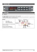
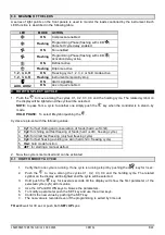
8.8  MEANING OF THE LEDS 

A series of light points on the front panels is used to monitor the loads controlled by the instrument. Each 
LED function is described in the following table


LED 

MODE 

ACTION 


ON 

Compressor enabled 


Flashing 

Programming Phase (flashing with LED 

Anti-short cycle delay enabled  


ON 

Fan enabled 


Flashing 

Programming Phase (flashing with LED 

Activation delay active 


ON 

Defrost active 


Flashing 

Drip time active 

1, 2, 3, 4, H 

ON 

Freezing cycle 1, 2, 3, 4 or hold mode active 

1, 2, 3, 4, H 

Flashing 

Instrument temporarily stop 


ON 

Alarm signalling 

AUX,  AUX2 

ON 

Aux or Aux2 enabled 

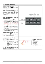
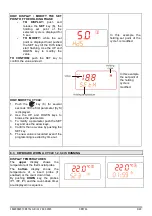
9.  HOW TO SELECT A CYCLE 

1.  Push the 

 to move among the cycles C1, C2, C3, C4 and the holding cycle. The related symbol on 

the display will be lighted and the cycle will be selected. 

NOTE:

 to pass from a cycle to another one simply push the 

 key when the controller is in stand –by 

mode. 

HOLD PHASE: 

 To select 

H

 symbol pushing the 


Cycles are pre-set with the following values: 
 

1. 

Cy1: 

for fast chilling and conservation of foods (hard +soft chill). 

2. 

Cy2: 

for chilling and fast freezing of foods (hard +soft + freezing cycle). 

3. 

Cy3:

 for direct fast freezing (only fast freezing cycle) 

4. 

Cy4: 

for fast freezing avoiding ice skin (hard chill + freezing cycle) 

5. 

HLd: 

hold mode function 

6. 

dEF: 

for starting a manual defrost


2.  Now the cycle is memorised and can be activated. 

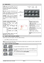
9.1  HOW TO MODIFY A CYCLE 

1. 

Verify that none cycle is running. If one cycle is running stop it by pushing the 


key for 3 sec. 

2. 

Push the 

  to move among the cycles C1, C2, C3, C4 and the holding cycle. The related 

symbol on the display will be lighted and the cycle will be selected 

3. 

Hold push the 

  key for several seconds till the display will show the first parameter of the 

selected cycle (cyS) with its value. 

4. 

Use the UP and DOWN keys to browse the parameters. 

5. 

To modify a parameter push the SET key and use the arrow keys.  

6. 

Confirm the new value by pushing the SET key.  

7. 

The new value is recorded even if the programming is exited by time out. 


TO exit: 

wait for 30 sec or push both 

SET+UP

 kyes. 


Summary of Contents for 378254

Page 1: ...mits before proceeding Dixell Srl reserves the right to change the composition of its products even without notice ensuring the same and unchanged functionality 2 SAFETY PRECAUTIONS Check the supply voltage is correct before connecting the instrument Do not expose to water or moisture use the controller only within the operating limits avoiding sudden temperature changes with high atmospheric humi...

Page 2: ...erating temperature range is from 0 0 to 60 C Avoid locations subject to heavy vibration corrosive gases or excessive dirt The same warnings have to be applied to the probes Ensure enought ventilation around the instrument 5 ELECTRICAL CONNECTIONS The instruments are provided with a screw terminal block to connect cables with a cross section up to 2 5mm2 for probes and digital input Spade on 6 3 m...

Page 3: ...e The lower display shows the temperature of the inserts probe or the count down timer To pass to the one insert probe to the another one use the DOWN key DISPLAY Temperature Timer or insert probe Alarm and status icons If an icon or LED is on the correspondent function is enabled If an icon or LED is flashing the correspondent function is delayed ...

Page 4: ...ayed 3 To restart the cycle press and release the key the cycle will restart from the some point at which it was interrupted 4 In any case the cycle automatically restarts after the PAU time HOW TO STOP A CYCLE hold pushed the START STOP button 2 till the yellow LED will be switched off HOW TO SET THE TIME RTC Hold pushed the DOWN key 5 till the Min label is displayed Use the UP and DOWN KEY to br...

Page 5: ...the set point of the holding cycle is modified HOW MODIFY A CYCLE 1 Push the key 6 for several seconds till the first parameter CyS is displayed 2 Use the UP and DOWN keys to browse the parameters 3 To modify a parameter push the SET key and use the arrow keys 4 Confirm the new value by pushing the SET key 5 The new value is recorded even if the programming is exited by time out 8 3 KEYBOARD WHEN ...

Page 6: ... or iSi label starti flashing and LED near the SET key is turned on Use the arrow key to modify the value and the SET key to confirm it 8 4 KEYBOARD WHEN THE HOLDING CYCLE IS RUNNING H HOW TO DISPLAY THE HOLDING REGULATION SET POINT While the holding cycle is running H icon lighted push the SET key and the holding set point is displayed on the UPPER display while the SETH label on the bottom displ...

Page 7: ...e SET key To exit the Printer menu push both SET UP keys or wait for 5 sec UP key browse the menu itP time printing interval PbP data to print PAr enabled the printing of the parameter map CyC enabled the printing of cycle parameters PtH enabled the printing during the holding phase PrS level Pr1 o Pr2 Pnu number of printing DOWN key back to the previous label 8 6 HOW TO START A MANUAL DEFROST Ass...

Page 8: ...H symbol pushing the Cycles are pre set with the following values 1 Cy1 for fast chilling and conservation of foods hard soft chill 2 Cy2 for chilling and fast freezing of foods hard soft freezing cycle 3 Cy3 for direct fast freezing only fast freezing cycle 4 Cy4 for fast freezing avoiding ice skin hard chill freezing cycle 5 HLd hold mode function 6 dEF for starting a manual defrost 2 Now the cy...

Page 9: ...o 12 0 res 0 1 C or 1 F i2P Insert probe 2 presence no YES no not present YES present i2o Insert probe 2 calibration 12 0 to 12 0 res 0 1 C or 1 F i3P Insert probe 3 presence no YES no not present YES present i3o Insert probe 3 calibration 12 0 to 12 0 res 0 1 C or 1 F rEM End cycle probe selection iPt rP it sets which probe stops teh the cycle thermostat probe or insert probe iPt insert probe rPt...

Page 10: ...ways switched on during the phases during the holding depends on this parameter The 2CH sets which compressor is used during the holding phase Second compressor operates on SET OAS SET is the value loaded during the holding phase of each cycle It starts oAt min after the first compressor The following table shows how it works Holding 2CH C1 C1 on 2CH C2 C2 on 2CH 1C2 C1 on C2 On OAt Second compres...

Page 11: ...Cn runs in parallel with compressors OFF during defrost o Y continuous mode on during defrost C1y runs in parallel with the first compressor on during defrost C2y runs in parallel with the second compressor on during defrost Cy runs in parallel with compressors on during defrost FSt Fan stop temperature 50 to 50 res 1 C or 1 F it used only if the EPP YES If the temperature detected by the evaporat...

Page 12: ...irst phase is ended rS1 Room probe Set point for the first phase 50 to 50 res 1 C or 1 F it prevents temperature from reaching a too low value during the hard cycle Pd1 Maximum time for first phase OFF to 4h00min res 10 min iS2 Insert probe set point 50 to 50 res 1 C or 1 F when the temperature measured by the three insert probes reaches this value the second phase is ended rS2 Room probe Set poin...

Page 13: ...When the box temperature reaches the rS2 value compressor is turned on end off so as to keep the temperature of the box at this value 11 3 3 Third phase Freezing cycle Freezing Cycle used to fast freeze foods The Freezing Cycle starts when the Soft Chill ends During the Freezing Cycle both compressor and fan are always on until the rS3 temperature is reached At this point compressor and fans are t...

Page 14: ...XB570L shall be mounted on vertical panel in a 150x31 mm hole and fixed using two screws 3 x 2mm To obtain an IP65 protection grade use the front panel rubber gasket mod RG L The temperature range allowed for correct operation is 0 to 60 C Avoid places subject to strong vibrations corrosive gases excessive dirt or humidity The same recommendations apply to probes Let the air circulate by the cooli...

Page 15: ...XB570L GB r1 1 23 03 2015 XB570L 13 20 13 XB07PR PRINTER OPTIONAL The XB570L is designed to work with the XB07PR The XB07PR kit is composed by 1 Printer 2 Power adapter 3 Connecting cables 13 1 PRINTER DIMENSIONS ...

Page 16: ...fore connecting cables make sure the power supply complies with the instrument s requirements Separate the probe cables from the power supply cables from the outputs and the power connections Do not exceed the maximum current allowed on each relay in case of heavier loads use a suitable external relay N B Maximum current allowed for all the loads is 20A 14 1 PROBE CONNECTIONS The probes shall be m...

Page 17: ...ge will start blinking 4 Turn OFF the instrument remove the Hot Key plug in the TTL serial cable and then turn it ON again At the end of the data transfer phase the instrument displays the following messages End for right programming The instrument starts regularly with the new programming Err for failed programming In this case turn the unit off and then on if you want to restart the download aga...

Page 18: ...on 1B Pollution degree normal Software class A Operating temperature 0 to 60 C 32 to 140 F Storage temperature 30 to 85 C 22 to 185 F Relative humidity 20 to 85 no condensing Measuring range 55 to 50 C 67 to 122 F NTC probe 40 to 110 C 40 to 230 F PTC probe 50 to 150 C 55 to 302 F Resolution 0 1 C or 1 F selectable Accuracy of the controller at 25 C 0 3 C 1digit 19 STANDARD VALUE OF THE CYCLES Cy1...

Page 19: ...E Pr2 Lod Local display rP Pr2 rEd Remote display rP Pr2 d1P Door switch polarity cL Pr2 Odc Open door control F C Pr2 dOA Open door alarm delay 5 Pr2 dLc Stop count down of running cycle y Pr2 rrd Regulation restart after door open alarm Y Pr2 d2F Second digital input function EAL Pr2 d2P Second digital input polarity cL Pr2 did Time delay for digital input alarm 5 Pr2 oA1 First configurable rela...

Page 20: ...m 30 Pr2 ALd Temperature alarm delay 15 Pr2 EdA Alarm delay after defrost 30 Pr2 tbA Silencing alarm relay YES Pr2 tCy Duration of last cycle Pr1 tP1 Duration of first phase of the last cycle Pr1 tP2 Duration of second phase of the last cycle Pr1 tP3 Duration of third phase of the last cycle Pr1 Adr Address for RS485 1 Pr2 bUt Buzzer activation at the end of the cycle 30 Pr2 tPb Type of probe ntc ...

Reviews: