24 • XR75CX I&O Manual
3. Press
+
to open the
Serial
tab of the
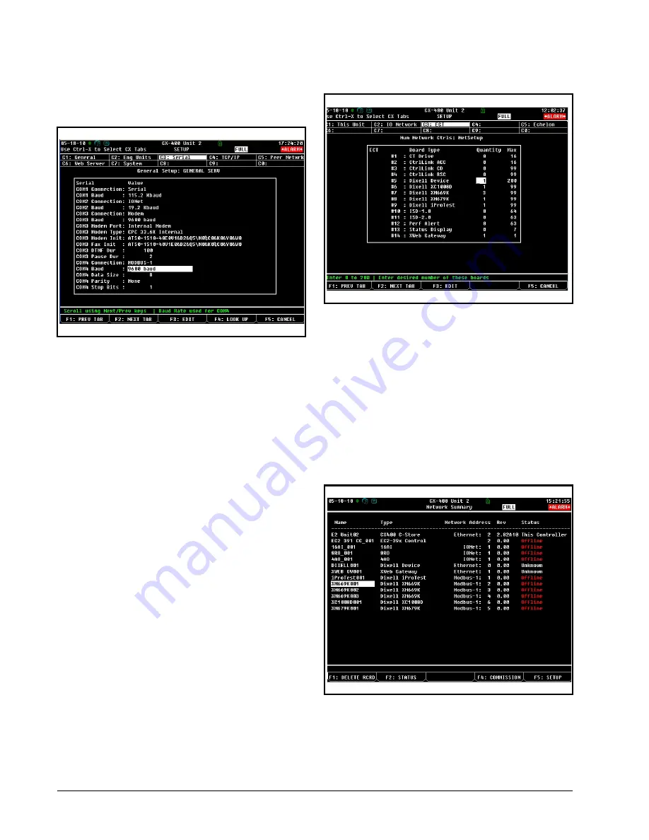
General Controller Info setup screens:
4. This screen will have a “Connection” field
for all COM ports on the E2. Highlight the
COM port connection field that will be used
for the device, and press
-
LOOK UP
.
From the list of network types, select
MOD-
BUS
.
5. Four fields will become visible underneath
the COM port connection field, which pertain
to the way the device communicates:
•
Baud -
Default setting is
19.2k
. The baud rate set-
ting should be set to match the baud rate of the
XR75CX device (
9600
). (All devices connected to
the same COM port should be set to the same baud
rate.)
•
Data Size -
Leave this field at the default value (
8
).
•
Parity -
Leave this field at the default value (
None
).
•
Stop Bits -
Leave this field at the default value (
1
).
6. Press
to save changes and exit.
18.1.2.Add and Connect the Device
To enable communications between E2 and the
XR75CX units, the devices must be added and ad-
dressed in E2.
1. Log in to the E2 with Level 4 access.
2. Press
-
Connected I/O
Boards and Controllers
.
3. In the
Num Network Ctrls: NetSetup
screen,
under the
ECT
tab, enter the number of de-
vices in the
Quantity
field. (
Max
shows the
maxium number of devices allowed on the
network.)
4. Press
to return to the
Network Setup
menu, then select
-
Network Summary
.
5. Locate the units you added to the network list
(press
and
to scroll through the list). If
desired, enter a new name for each device in
the
Name
field.
6. By default, each device in the network list has
a board number of 0. To set the address and
begin communication, choose the device and
press
. In the list of MODBUS devices,
Figure 18-3
- Serial Communications Manager Screen
Figure 18-4
-
Num Network Ctrls: NetSetup Screen
Figure 18-5
- Network Summary Screen
Summary of Contents for 318-6030
Page 2: ......
Page 4: ......
Page 27: ...Other Messages Connections 21 16 Connections Figure 16 1 XR75CX Connections ...
Page 36: ......


