
Types 1301F and 1301G
5
Maintenance
Regulator parts are subject to normal wear and must be
inspected and replaced as necessary. The frequency
of inspection and parts replacement depends on the
severity of service conditions and the requirements of
local, state and federal rules and regulations.
Instructions are given below for disassembly and
assembly of parts.
!
WARNING
To avoid personal injury or equipment
damage from sudden release of pressure
or explosion of accumulated gas, do not
attempt any maintenance or disassembly
without first isolating the regulator from
system pressure and relieving all internal
pressure from the regulator.
Disassembly
The following procedure describes how to completely
disassemble the regulator. When part replacement
or inspection is required, complete only those steps
necessary to accomplish the job. Key numbers
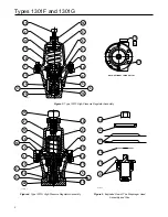
referenced are shown in Figure 3 for the Type 1301F
regulator and in Figure 4 for the Type 1301G regulator
unless otherwise indicated.
1.
Loosen the locknut (key 18).
2.
Turn the adjusting screw (key 15)
counterclockwise to remove spring compression.
3.
Remove the bottom cap (key 3), bottom cap
O-ring (key 14) and spring (key 10).
4.
Unthread the valve disk assembly (key 6) from
the yoke (key 4).
5.
Remove the valve disk collar (key 22) from the
valve disk assembly.
6.
Remove the spring case cap screws (key 16),
and separate the spring case (key 2) from the
body (key 1).
7. Remove the upper spring seat and spring
(keys 9 and 11).
8. Refer to Figure 5. Unscrew the diaphragm
locknut (key 19), and remove the diaphragm
plate (key 8), the two diaphragms (key 7) and the
diaphragm plate gasket (key 13).
9.
Remove the screws (key 17) from the yoke, and
take the lower and upper halves of the yoke out
of the body. The yoke halves are a matched set
and need to be kept together.
10.
Unscrew the orifice (key 5). Examine seating
edge of orifice. Replace with a new part if worn
or nicked.
Assembly
This procedure assumes that the regulator was
completely disassembled. If not, start these
instructions at the appropriate step. Key numbers used
are shown in Figure 3 for the Type 1301F regulator
and in Figure 4 for the Type 1301G regulator unless
otherwise indicated.
1.
Screw the orifice (key 5) into the regulator.
2.
Insert both halves of the yoke (key 4) into the
regulator, and fasten them together with the
screws (key 17). The yoke halves are a matched
set and need to be kept together.
3.
The valve disk assembly (key 6) has two valve
disks, one on each end. Inspect both valve disks,
and select the one to be used. Thread the valve
disk assembly into the yoke so that the disk to be
used is positioned against the orifice. Thread the
valve disk collar (key 22) onto the exposed end of
the valve disk assembly.
4.
Place the bottom cap O-ring (key 14) on the
bottom cap (key 3). Place the spring (key 10) in
the bottom cap, and thread it into the regulator.
5.
Put the body gasket (key 12) on the regulator
body (key 1).
6. Refer to Figure 5. Place the diaphragm plate
gasket (key 13), two diaphragms (key 7), and
the diaphragm plate (key 8) on the yoke (key 4).
Make sure the diaphragm convolutions are toward
the spring, and secure the parts by threading the
diaphragm locknut (key 19) onto the yoke.
7.
Place the regulator spring (key 11) and upper
spring seat (key 9) on the diaphragm plate.
8.
Position the spring case (key 2) over the spring and
on the regulator body. Orient the spring case vent or
vents as necessary. Insert the cap screws (key 16),
and tighten them only finger-tight.
9.
Thread the adjusting screw and locknut (keys 15
and 18) into the spring case just far enough to
slightly compress the spring. Securely tighten the
cap screws (key 16), and refer to the Startup section
for adjustment procedures.


