


User Manual
Chapter 3 – Installation Procedure
N
N
e
e
t
t
w
w
o
o
r
r
k
k
P
P
o
o
w
w
e
e
r
r
S
S
w
w
i
i
t
t
c
c
h
h
Page
3-3
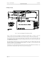
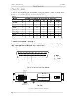
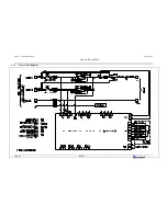
3.3.3 Cable
connections
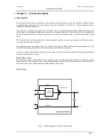
Following are the set of external power cables, which are connected to the Network Power Switch equipment –
•
Input source 1 – Line
•
Input source 2 – Line
•
Input source 1 – Neutral
•
Input source 2 – Neutral
•
Output – Line
•
Output – Neutral
•
Earthing
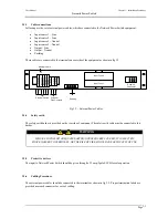
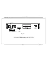
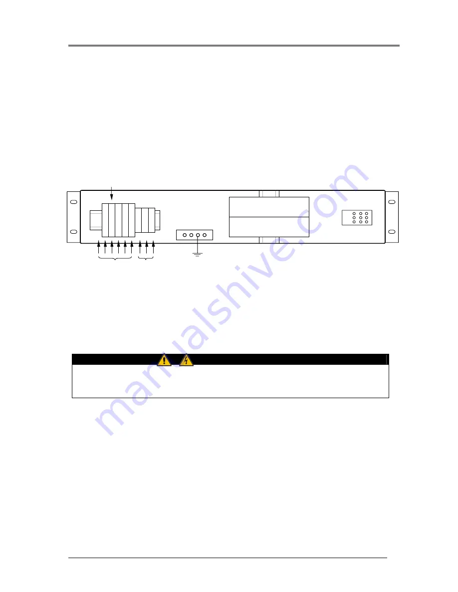
These cables are connected to the terminals on rear side of the equipment as shown in fig 3.2
Fig 3.2 – External Power Cables
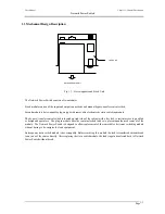
3.3.4 Safety
earth
The safety earth busbar is provided on the rear side of equipment .The safety earth cable must be connected to this
busbar.
WARNING
FAILURE TO FOLLOW ADEQUATE EARTHING PROCEDURES CAN RESULT IN ELECTRIC
SHOCK HAZARD TO PERSONNEL, OR THE RISK OF FIRE, SHOULD AN EARTH FAULT OCCUR.
3.3.5 Protective
devices
The input to Network Power Switch should be given through a 32 amp, 2pole ELCB for safe operation.
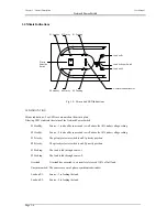
3.3.6 Cabling
Procedure
The external power cables should be connected to the terminals as shown in fig 3.2. Proper termination labels are
provided near each connector for ease of cabling.
O
/p Li
ne
Input Fuse 1
Input Fuse 2
Ne
ut
ra
l -
2
Ne
ut
ra
l -
1
Snap-on
Connector
External Cables
I/p Li
ne
-
2
I/p Li
ne
-
1
Earthing
Co
m
m
on
S2
H
eal
thy
S1
H
eal
thy
Co
m
m
on
S2
H
eal
thy
S1
H
eal
thy
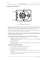
Potential
Free Contacts
External Cable
Summary of Contents for 110V
Page 4: ......
Page 10: ......
Page 26: ......
Page 31: ...Chapter 4 User Manual N Ne et tw wo or rk k P Po ow we er r S Sw wi it tc ch h 02 04 Page 5 5 ...