


Chapter 1 - General Description
User Manual
N
N
e
e
t
t
w
w
o
o
r
r
k
k
P
P
o
o
w
w
e
e
r
r
S
S
w
w
i
i
t
t
c
c
h
h
Page 1-6
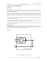
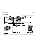
1.6 Potential free contacts
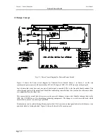
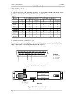
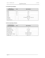
The Network Power Switch status can be checked with the 37-pin D-type connector, located on the rear end. This is a
potential free contact, and gives following indications as shown in Table 1-1 –
Table 1-1
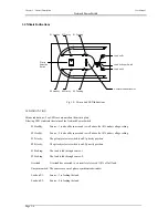
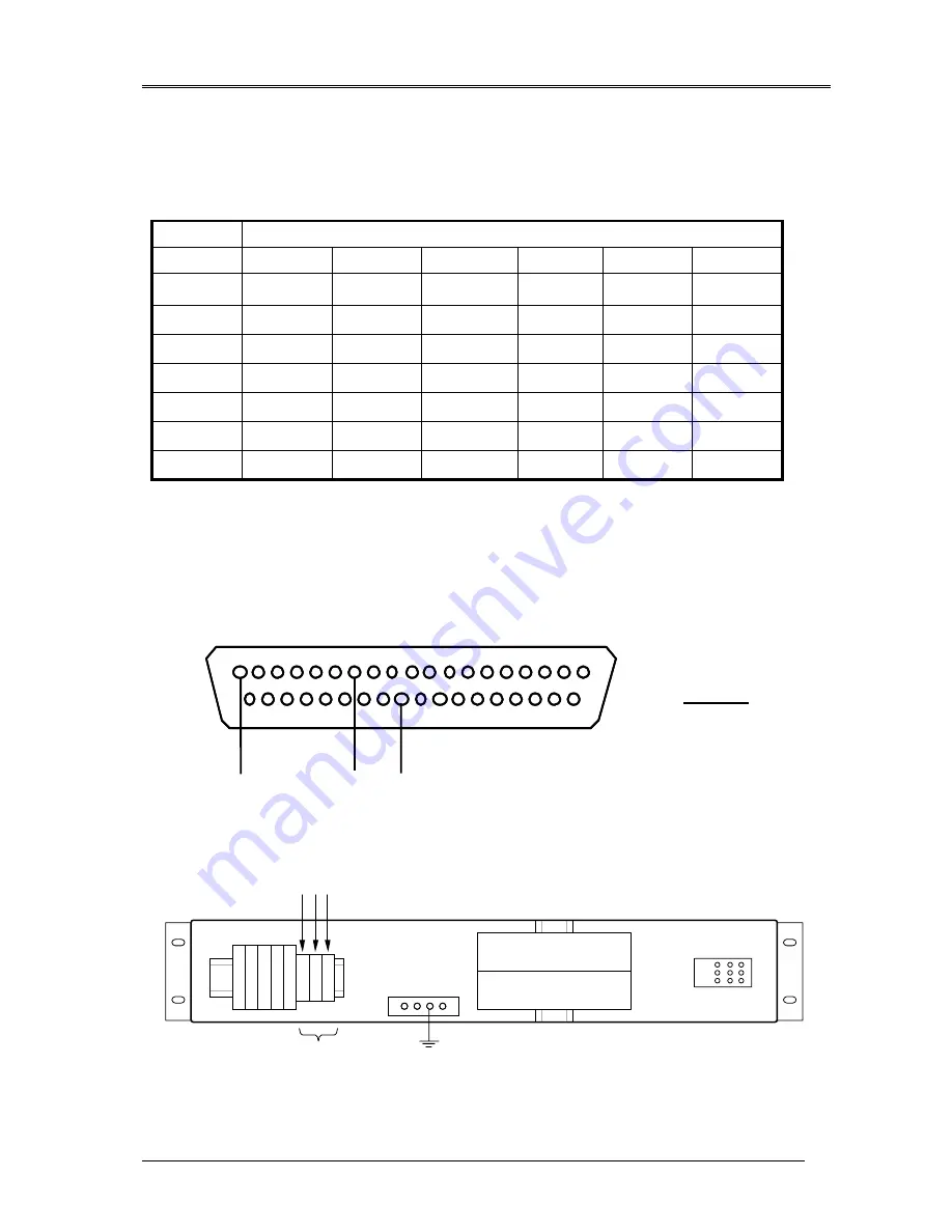
The pin details for this connector is shown in fig 1.6
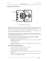
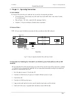
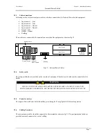
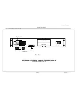
Two potential free contacts indicating Source 1 and Source 2 Healthy conditions are taken from this 37 pin D type
connector and terminated at rear terminal connectors, as shown in figure 1.7.
Fig 1.6 – Pin details for 37 pin D-type Connector
Fig 1.7 – Potential free contacts Connectors
19
18
37
36
35
17
Unsynch
19
34
16
15
14
33
S2 Feed
19
13
32
31
30
12
S2 Healthy
19
29
11
10
9
28
S1 Healthy
19
8
27
26
25
7
S1 Feed
19
24
6
5
4
23
Priority
19
21
3
2
1
20
Overload
Common
NO
NC
Common
NO
NC
Termination available of 37 pin D-type connector
Status
19
18
37
36
35
17
Unsynch
19
34
16
15
14
33
S2 Feed
19
13
32
31
30
12
S2 Healthy
19
29
11
10
9
28
S1 Healthy
19
8
27
26
25
7
S1 Feed
19
24
6
5
4
23
Priority
19
21
3
2
1
20
Overload
Common
NO
NC
Common
NO
NC
Termination available of 37 pin D-type connector
Status
1
2
19
3
4
5
6
7
8
9
10
11
12
13
14
15
16
17
18
20
37
21
22
23
24
25
26
27
28
29
30
31
32
33
34
35
36
52
50
51
Pin Details
50
–
S2 Healthy
51
–
S1 Healthy
52
-
Common
O
/p L
ine
Input Fuse 1
Input Fuse 2
Rear View
N
eutr
al
-
2
N
eutr
al
-
1
I/p L
ine
-
2
I/p L
ine
-
1
Co
m
m
on
S
2 H
eal
th
y
S
1 H
eal
th
y
Co
m
m
on
S
2 H
eal
th
y
S
1 H
eal
th
y
52 50 51
POTENTIAL
FREE CONTACTS
Summary of Contents for 110V
Page 4: ......
Page 10: ......
Page 26: ......
Page 31: ...Chapter 4 User Manual N Ne et tw wo or rk k P Po ow we er r S Sw wi it tc ch h 02 04 Page 5 5 ...