


V250 Valve
Instruction Manual
Form 5206
April 2004
2
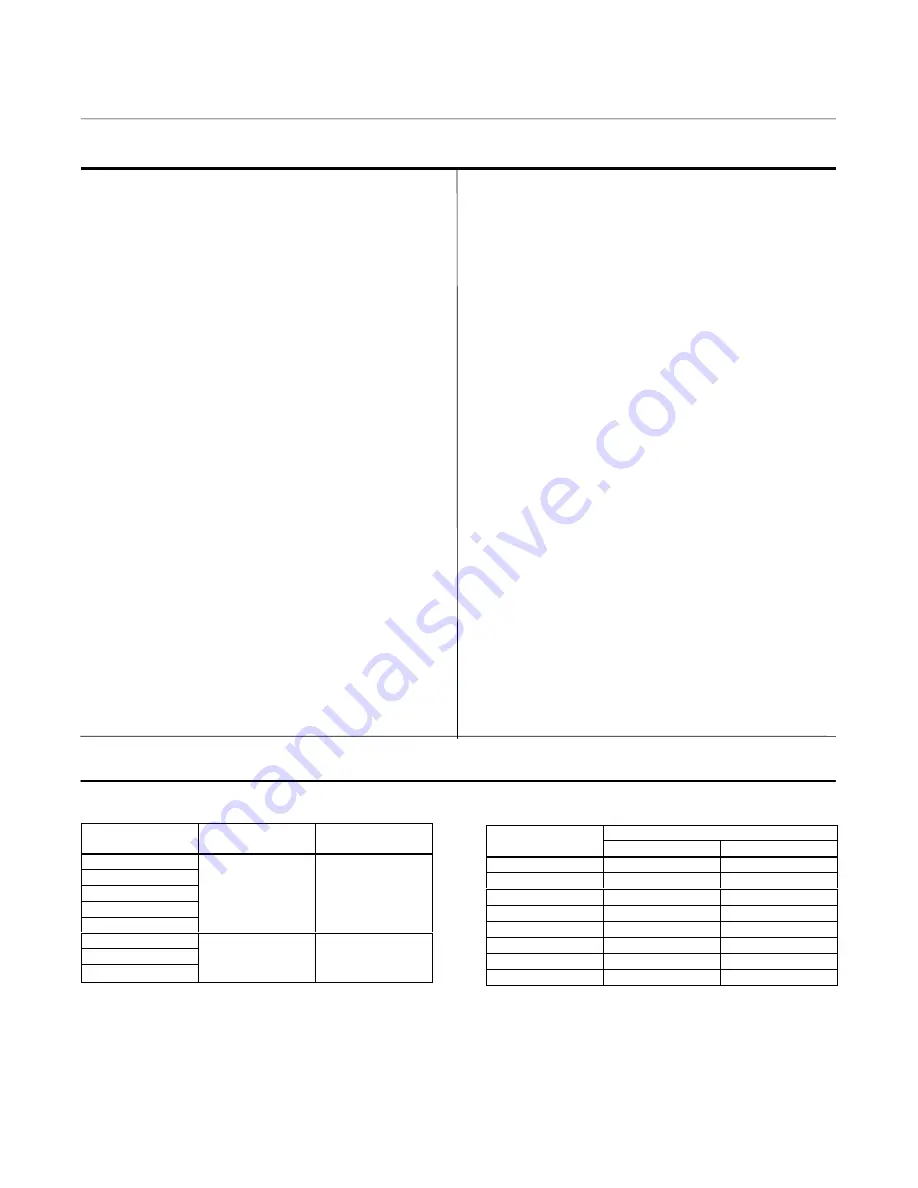
Table 1. Specifications
Valve Sizes and End Connection Styles
4 through 24-inch flangeless valves retained by
line flange bolts and designed to fit between ANSI
raised-face or ring-type joint flanges. See table 2
for valves that install between ANSI flanges
Maximum Inlet Pressure
(1)
Consistent with applicable pressure-temperature
ratings listed in table 2
Maximum Allowable Shutoff Pressure Drop
(1)(2)
Single-Seal and Dual-Seal Construction: 155
bar (2250 psi) at 38
_
C (100
_
F) and 103 bar (1500
psi) at 82
_
C (180
_
F) except where further limited
by the pressure-temperature rating of the valve
body
Flow Ring Construction: Limited by the
pressure-temperature rating of the valve body
Seal Material Temperature Capability
(1)
Single-Seal and Dual-Seal Construction:–46 to
82
_
C (–50 to 180
_
F) with LCC or stainless steel
valve bodies
Flow Ring Construction with Nitrile O-Rings:
–46 to 93
_
C (–50 to 200
_
F) with LCC steel and
stainless steel valve bodies
Flow Ring Construction with Fluoroelastomer
O-Rings: –46 to 204
_
C (–50 to 400
_
F) with LCC
steel and stainless steel valve bodies
Flow Characteristic
Modified equal percentage
Flow Direction
Forward Flow: Single seal construction is
standard for forward flow (see figure 4)
Bidirectional Flow: Flow ring construction can
be used for either forward or reverse flow (see
figure 5)
Bidirectional Shutoff: Dual seal construction is
required to provide shutoff for bidirectional flow
(see figure 12)
Shutoff Classification
Single Seal and Dual Seal Constructions:
0.0001% of maximum valve capacity (less than
1% of Class IV, ANSI/FCI 70-2)
Flow Ring Construction: 1% of maximum valve
capacity
Maximum Ball Rotation
90 degrees
Actuator Mounting
Right-hand or left-hand mounted as viewed from
the valve body inlet for forward flow
Approximate Weights
See table 3
1. The pressure/temperature limits in this manual and any applicable standard or code limitation for valve should not be exceeded.
2. Maximum allowable shutoff pressure drops are further limited for the following constructions. The 12-inch size with Nitronic 50 drive shaft is limited to 128 bar (1862 psi) from –46 to 59
_
C
(–50 to 139
_
F) and to 130 bar (1490 psi) at 93
_
C (200
_
F). The 16-inch size with 17-4PH steel, with 2.5 inch splined drive shaft is limited to 69 bar (1000 psi), and with the Nitronic 50, 2.5 inch
splined drive shaft is limited to 55 bar (795 psi) at all service temperatures. The 24-inch size with Nitronic 50 drive shaft is limited to 92 bar (1336 psi) at all service temperatures.
Table 2. ANSI Rating and Flange Compatibility
Valve Size,
Inches
Inlet Pressure
Capability
ANSI Flange
Compatibility
4
6
Consistent with
Class 600 or 900 raised
8
Consistent with
Class 600 or
900 (ASME B16.34)
Class 600 or 900 raised
face or ring-type joint
flange (ASME B16.5)
10
Class 600 or
900 (ASME B16.34)
face or ring-type joint
flange (ASME B16.5)
12
16
Consistent with Class
Class 600 raised face
20
Consistent with Class
600 (ASME B16.34)
Class 600 raised face
or ring-type joint flange
(ASME B16.5)
24
600 (ASME B16.34)
or ring-type joint flange
(ASME B16.5)
Table 3. Approximate Weights
VALVE SIZE,
INCHES
WEIGHT
VALVE SIZE,
INCHES
Kilograms
Pounds
4
73
160
6
132
290
8
222
490
10
345
760
12
431
950
16
771
1700
20
1814
4000
24
2404
5300


