


Embedian, Inc.
44
SBC-SMART-MEN User’s Manual Document Revision v.1.0
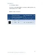
3.1.3.11. JTAG Connector: CN3 on Module
JTAG functions for CPU debug and test are implemented on separate
small form factor connector (CN3:
JST SM10B-SRSS-TB
, 1mm pitch R/A
SMD Header) on SMARC module. The JTAG pins are used to allow test
equipment and circuit emulators to have access to the Module CPU. The
pin-outs shown below are used:
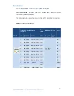
The following table shows the pin-out of the CN3 (on module) JTAG
connector.
CN3: Location on Board, D4
JTAG Connector:
JST SM10B-SRSS-TB, 1mm pitch
R/A SMD Header
Edge
Finger
Sitara AM335x CPU
Type
Header
Pin
Signal Name
Function
Pin#
Ball
Mode
Signal
Name
1
VDD_33A
JTAG I/O
Voltage
(sourced by
Module)
P
2
nTRST
JTAG
Reset,
active
low
B10
nTRST
B10
I
3
TMS
JTAG
mode
select
C11
TMS
C11
I
4
TDO
JTAG
data
out
A11
TDO
A11
O
5
TDI
JTAG data in
B11
TDI
B11
I
6
TCK
JTAG clock
A12
TCK
A12
I
7
RTCK
JTAG return
clock
I
8
GND
Ground
P
9
MFG_Mode#
Pulled low to
allow in-circuit
SPI ROM
update
I
10
GND
Ground
P


