background image

9


Nighthawk Pro 200


yinyanmodel.com 

channel  using  the  drop-down  box  on  the  right. You  can  use  the  slider  to  set  a  ppm  range  your  auxiliary  channel  will 

operate. Check your settings you have made in modes and save them by clicking "SAVE" on the bottom-right corner. 

When a desired mode is selected by a switch on the AUX channel, selected mode name will be highlighted and yellow 

indicator  will  correspond  with  transmitted  ppm  value.  (NOTE:  Some  modes  need  to  be  selected  at  the  same  time  to 

function  correctly.  Some  modes  will  only  be  shown  when  the  corresponding  sensors  are  connected  or  active,  for 
example, the “Baro” mode will not appear if there is no barometer sensor connected or active.) 


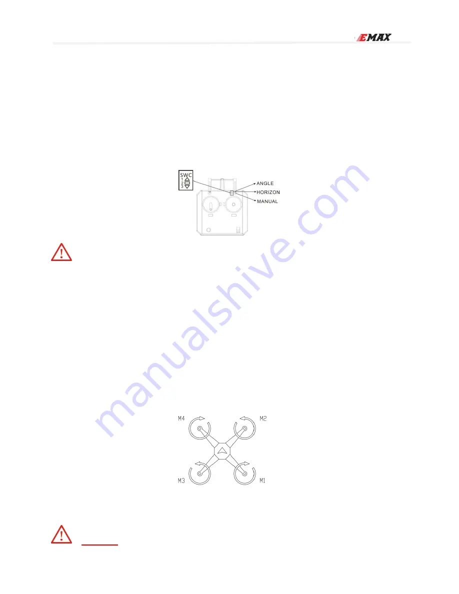
RTF MODE SELECTION DIAGRAM (Does not apply to PNP)


The  radio  in RTF  version  has  a  fail-safe  function. SWC  switch  is  the  flight  mode  selection  switch.  SWC  switched  to 

position 1 is ANGLE. Position 2 is HORIZON and 3 is MANUAL. Please refer to the diagram below. 


Caution:  We  do  not  recommend  selecting  MAG  to  avoid  big  current  interference 
with the compass.


COPTER TESTING


Please make sure to REMOVE PROPELLERS before performing test


1

Connect Radio Receiver and flight controller 

2

Please select "Raw Sensor Data" 

3

Rotate copter to check all sensor are correct (sensor data should change according to copter rotation) 

4

Please select "Motor Test Mode” 

5

Turn on Radio Transmitter 

6

Connect battery with XT60 connector to power on the copter. 

7

Use Radio Transmitter to arm motors, and the flight controller light indicators will turn green. 


Process to Arm and Disarm motors are shown below (Mode 2 Transmitter used as example)


8

Move throttle stick UP 

9

Use the transmitter sticks to control pitch, roll and yaw. Observe the Motor Throttle bars under "Motor” tab and 

confirm the output values correspond correctly to your input commands. 

10

Test motor direction: To determine the motor direction, use a piece of paper    to rub on side of bell. Please be 

careful and confirm correct direction per motor. (Motor direction should be the same as the figure shown below)   


Step 4: Installation 


Caution: 

Summary of Contents for Nighthawk Pro 200

Page 1: ...ro 200 Please follow the instruction manual to install and configure your Nighthawk Pro 200 After completing the instruction manual use the configurator GUI to configure flight controller settings for the Nighthawk Pro 200 Please refer to this link to learn more http yinyanmodel com en DownList asp ...

Page 2: ... Troubleshoot 11 Appendix 12 Reminder 12 Disclaimer Please read the disclaimer carefully before using this product By using this product you hereby agree to this disclaimer and signify that you have read them carefully and completely This product is not suitable for people under the age of 18 Adult supervision is highly recommended for kids under the age of 18 Our Nighthawk Pro 200 features open s...

Page 3: ...features a great price amazing value and technology compared to competitor s products Race ready motors right out of the box The RS2205 motors are the Champion s choice for competition Now you can get the best Modular design with the ability to switch out main components without having to solder to small connectors Full LED coverage to help gauge orientation in the brightest of days and darkest of...

Page 4: ...4 2CW 2CCW Model Size Weight PNP RTF Wheelbase L x W x H Not including propeller 200mm Package L x W x H 260mm x 185mm x 65mm Nighthawk Pro 200 L x W x H 207mm x 165mm x 43mm Not including antenna Camera CCD 600TVL Propeller T5050 Tri Blade Propeller Flight controller SP Racing F3 ACRO Motor RS2205 2300KV CW THREAD ESC Lightning_S 25A BLHeli_S Flight weight g 370g Not including battery ...

Page 5: ...5 Nighthawk Pro 200 yinyanmodel com Overall View Explode View ...

Page 6: ... Driver installed continue on to Step 2 1 Please choose the compatible driver for your computer Link to Driver http url cn 7SnpKh 2 Install the Driver onto your computer following the installation windows 3 Connect the flight controller to the computer using a Micro USB cable 4 Follow steps to complete installing the driver 2 Configuration Software Installation 1 Please install Google Chrome Web B...

Page 7: ... configurator 2 Flight Controller Setting Basic Accelerometer and Magnetometer Calibration Please select SETUP Calibrate Accelerometer Calibrate Magnetometer If Supported 1 Calibrate Accelerometer Place the Nighthawk Pro 200 on a leveled surface then select Calibrate Accelerometer Once the accelerometer calibration is complete date will be saved automatically Note Starting or ending accelerometer ...

Page 8: ...onfirmation will sound move the Master Slider to minimum and wait for the MINIMUM throttle confirmation sound After the minimum throttle confirmation sound you will hear a final confirmation sound ESC calibration is complete MODE SELECTIONS 1 Please select Modes Flight Modes ARM ANGLE HORIZON MAG HEADFREE etc If need to add another mode please click Add Range When desired mode is selected AUX Chan...

Page 9: ... diagram below Caution We do not recommend selecting MAG to avoid big current interference with the compass COPTER TESTING Please make sure to REMOVE PROPELLERS before performing test 1 Connect Radio Receiver and flight controller 2 Please select Raw Sensor Data 3 Rotate copter to check all sensor are correct sensor data should change according to copter rotation 4 Please select Motor Test Mode 5 ...

Page 10: ...r is 25mw Toggling the switch towards the rear end of copter is 600mw The default power output is 25mw Step 5 Test flight After completion of initial setup and testing It is finally time to take flight Turn on the Radio Transmitter and connect a 3S 4S LiPo to the copter Place the Nighthawk Pro 200 in the center of the test flight field Safe flying zone As soon as the Flight controller completes it...

Page 11: ...n and motors do not arm Please redo Accelerometer Calibration 3 Copter cannot lift off the ground Please check Propeller direction Please check Battery voltage 4 Copter arms but one or more motors are not spinning Please check connection between motor and ESC 5 No Video feed on monitor or goggles Please check Video Transmitter and Receiver connections Please check if proper video BAND and CHANNEL ...

Page 12: ...oard 2 Power the Flight Controller board by USB 5v Only POWER light will be ON at this time Then disconnect the BOOT pad If during this period the other 2 LEDs light or you cannot continue to the next step please repeat the operation 3 After entering boot mode perform firmware update Thank you for purchasing an EMAX Product Caution Safety comes first Make sure to fly in safe zone This product may ...

Reviews: