EM TEST
AutoWave
Manual for Operation
V 5.9.1
9 / 45
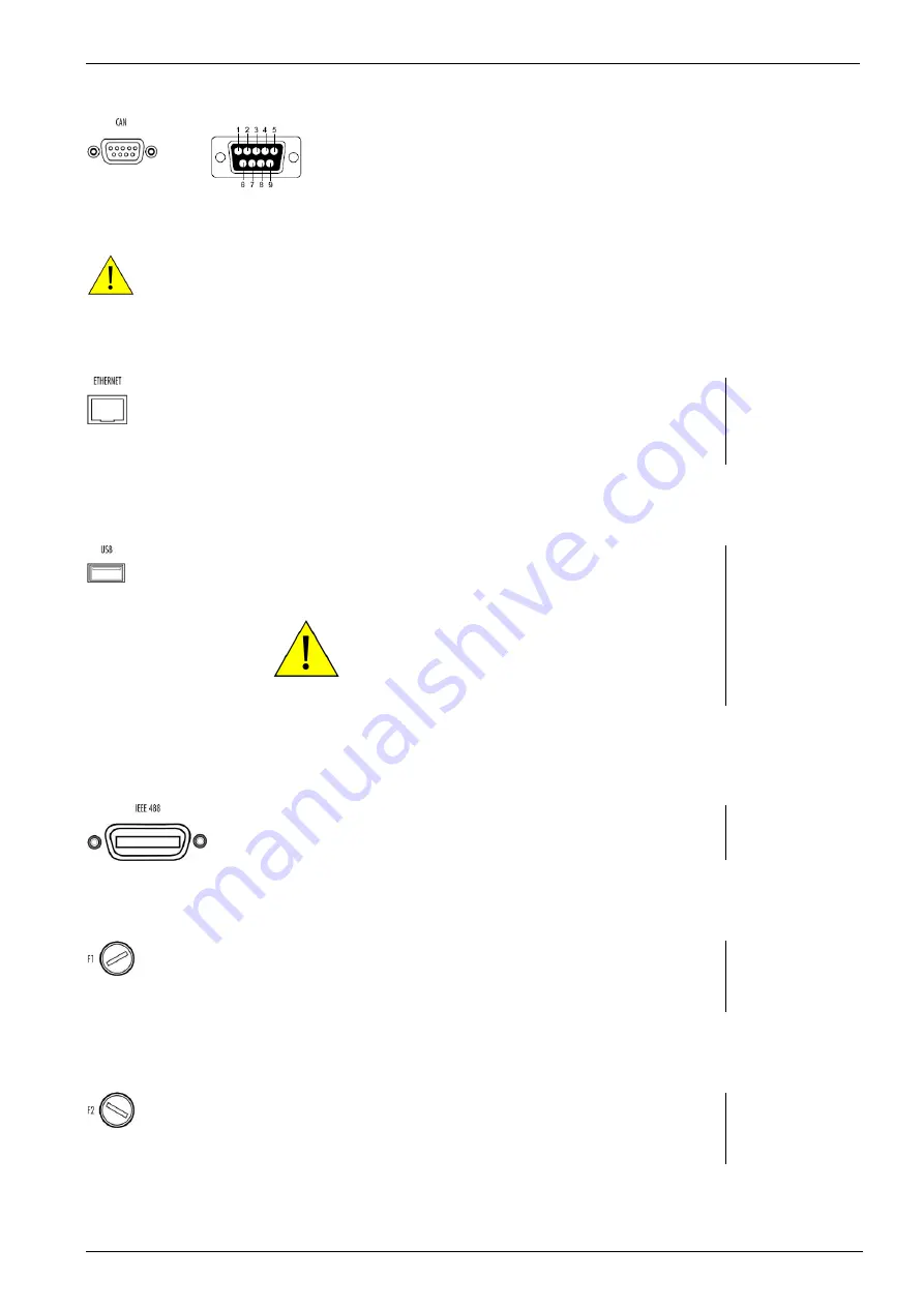
3. CAN port
CAN port 9 pole Sub D female connector
The Philips PCA82C251 CAN transceiver for 24V
system serves as the interface between the CAN
protocol controller and the physical bus. It is primarily
intended for applications (up to 1 Mbaud)
The CAN- BUS is function is inactive
Pin assignment
1: nc
2: CAN_L
3: CAN GND
4: nc
5: CAN SHLD
6: CAN GND B
7: CAN_H
8: nc
9: +VCAN
4. Ethernet port
The network controller supports a 10 / 100Base-
Tinterface. The device auto-negotiates the use of a
10Mbit/sec or 100Mbit/sec connection.
Pin assignment
1: TXD+
2: TXD
3: RXD+
4: RXD-
5. USB port
USB memory port for data transfer to or from a
memory stick.
The power contacts for USB devices are not protected. They are
suitable to supply connected USB devices with a maximum of
500mA
power dissipation. Don’t supply external USB devices
with a higher power dissipation through this interface.
Pin assignment
1: GND
2: +DATA
3: -DATA
4: VCC
6. GPIB / IEEE 488 port
Parallel interface GPIB / IEEE 488, IEEE 488
interface with IEEE connector.
7. Fuse F1
Fuse F1 for DC power supply
Fuse type :
3.15 slow blow
Dimension :
5 x 20mm
8. Fuse F2
Fuse F1 for AC power supply
Fuse type :
1A slow blow
Dimension :
5 x 20mm


