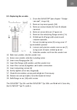
elysator 100c Operating Instructions Manual Download Page 12

12

8.2. Sludge removal

De-sludge the ELYSATOR® regularly. Exactly how often this is required 

depends on the amount of sludge. We recommend sludge removal once a 

year.

Procedure:

1. 

Close valve (7) in the input line

2. 

Close valve (7) in the output line

3. 

Unscrew air vent (4)

4.  Remove the cap from drain valve (3)

5.  If required, connect a hose and route it to a bucket or drain

6.  Pull out magnet (9)

7.  Open the drain valve (if blocked, use a screwdriver or wire to clear it)

8.  Release the vacuum by pressing on the air valve on air vent connection 

(4)

9.  Connect drain (3) to the fresh water supply

10.  Fill with fresh water (press on the air valve on air vent connection (4))

11. 

Drain the ELYSATOR® as described in steps 1-8

12. 

Repeat the procedure until the water comes out clean when draining

13. 

Fill the ELYSATOR® with demineralised water via the drain valve, as 

described in steps 9-10

14.  Close drain valve (3) and screw on the cap

15.  Screw on air vent (4)

16.  Open supply and output valves (7)

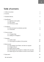
Summary of Contents for 100c

Page 1: ...www elysator com Installation Function Operation Service Operating instructions ELYSATOR Typ 50c 100c...

Page 2: ......

Page 3: ...onnection 8 6 Commissioning 6 1 Filling venting 9 6 2 Setting the throughput 9 7 Operation 7 1 System water 10 7 2 Checking the condition of the anodes 10 8 Maintenance 8 1 Interpreting the indicator...

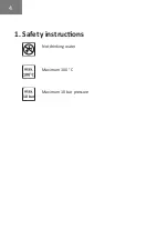
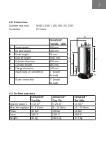
Page 4: ...4 1 Safety instructions Not drinking water Maximum 100 C Maximum 10 bar pressure 10 bar...

Page 5: ...functions are combined into one appliance pH regulation by means of a sacrificial anode Micro gas bubble separator Magnetic flow filter 3 Standard delivery 2 plug 1 red brass 2 twin connector 1 3 4 r...

Page 6: ...th insulation 2 Indicator 3 Drain valve 4 Vent valve with gasket and coupling 5 Elbow 2x 6 Line regulating valve 7 Shut off valve 2x 8 Coupling 9 Magnet 10 Cover plate 2 part 11 Input 1 2x 12 Output 1...

Page 7: ...E Cylinder diameter 420 mm F Cylinder height 685 mm G Flange diameter 140 mm Input output connection 1 inside thread Drain connection 1 inside thread 4 3 Performance data ELYSATOR Typ 50c ELYSATOR Ty...

Page 8: ...arated out efficiently an installation position close to the diffusion point underfloor heating should be selected The appliances in the ELYSATOR industrial series are designed for installation in a s...

Page 9: ...g the air 6 2 Setting the throughput Set the throughput according to the values in the chart in chapter 4 3 A On indicator 1 mark the reference value for setting the valve B Pull ring 2 to open the sl...

Page 10: ...During operation the ELYSATOR function must be checked every 6 months This is shown on the wear indicator on the duct As long as the wear indicator is in the green zone the anode is operating normally...

Page 11: ...OR and fill it with tap water If after one day with the shut off valves closed the wear indicator reads a higher value than before then the system is OK The ELYSATOR can then be re filled with deminer...

Page 12: ...9 7 Open the drain valve if blocked use a screwdriver or wire to clear it 8 Release the vacuum by pressing on the air valve on air vent connection 4 9 Connect drain 3 to the fresh water supply 10 Fill...

Page 13: ...a size 10 open ended spanner 9 Slide the anodes out from the anode tree 10 Slide new anodes into the anode tree 11 Screw new anodes onto the isolating screw 12 Insert new flange gasket 6 13 Insert the...

Page 14: ...anode 8 5 Replacing the wear indicator and the control button Fig 7 3 1 Remove top cover panels 10 2 Remove contact blade 3 from the blade terminal 3 Loosen flange screw 4 with cable connection 4 Rem...

Page 15: ......

Page 16: ...Service booklet Installer Date of installation Project Device no Sludge removal interval Maintenance interval Date Job Meter mA Company signature...

Reviews: