background image

Printer Tag

Sense Through

Hole Position

The TLP 2046 printer uses a moveable sensor
to detect index holes/notches in tag stock. The
sensor position is indicated by the green arrow
at the front of the label guide that is visible with
the printhead open. The sensor can be moved
by  squeezing the two locking  tabs, located
under the label guide, and sliding the sensor in
or out. For proper sensing, ensure that the
sensor is aligned with the center portion of the
index hole/notch.

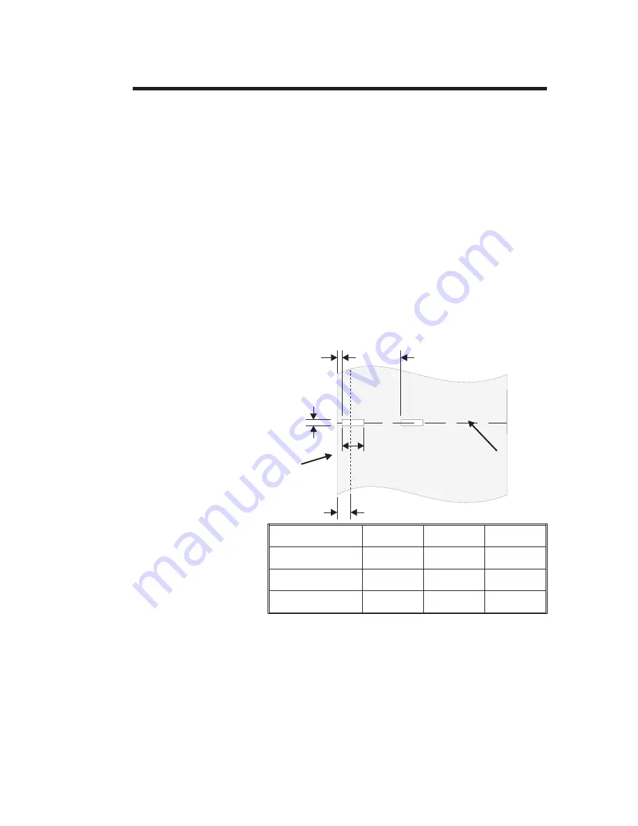
The following dimensions show the required
position of the Sense-Through (“Notch”) hole
on tag stock for the TLP2046 printer.

Dimension

Min.

Max.

Nominal

A

.236"

None

.512"

B

.079"

.512"

.118"

C

.098"

.216"

N/A

B

C

A

.314 Nominal Sensor Location

min.

max.

Inside Edge

of Tag Stock

Tag

Tear-away

Figure C-2

Tag Position

Sensing Layout

Trouble Shooting

980003-003 Rev. A

47

Summary of Contents for TLP2044

Page 1: ...User s Manual No 980003 003 Rev A 1996 Eltron International Inc TLP2046 User s Manual ...

Page 2: ......

Page 3: ...and mark the RMA number clearly on the outside Ship the equipment freight prepaid to the address listed below Eltron Repair Administration 41 Moreland Road Simi Valley CA 93065 805 579 1800 FAX 805 579 1808 COPYRIGHT NOTICE This document contains information proprietary to Eltron International Incorporated This docu ment and the information contained within is copyrighted by Eltron International I...

Page 4: ...s equipment has been tested and found to comply with the limits of a Class A digital device pursuant to Part 15 of the FCC Rules These limits are designed to provide reasonable protection against harmful interference when the equipment is operated in a commercial environment This equipment generates uses and can radiate radio frequency energy and if not installed and used in accordance with the in...

Page 5: ...or Tags 16 Transfer Ribbon Loading 25 Label Rewinding and Auto Dispensing 28 Label Variations and the Label Sensor 35 AutoSense Gap Sensor Adjustment 36 Cleaning The Print Head 37 Replacing the Printer Memory Backup Battery 38 Appendix A Trouble Shooting 43 Appendix B Supplies and Accessories 53 Appendix C Windows Printer Driver 57 980003 003 Rev A v ...

Page 6: ...vi 980003 003 Rev A ...

Page 7: ... or without bar codes from any DOS Windows or ASCII based compatible computer Features High speed direct thermal and thermal trans fer printing for reliability Supports over 20 types of bar code sym bologies Download forms fonts and graphics perma nently to printer memory or removable memory cartridges High resolution print head for sharp graphics and text Built in label rewinder for batch process...

Page 8: ...gy that accu mulates on the surface of the human body or other surfaces can damage or destroy the print head or electronic components used in this device Damage to the Memory Cartridge configura tion switch or the printer interface connector may result from placing the TLP2046 printer on it s backside during unpacking or handling Remove the tape used to secure the memory cartridge to the back pane...

Page 9: ...over by lifting the lip on the lower right side of the cover Remove the tape securing the label rewind clip to the label rewind tube Lift To Open S T E P P E R M O TOR 2 50m m 4 100mm Remove Tape Getting Started 980003 003 Rev A 3 ...

Page 10: ... open the printer s front door The door has a magnetic latch for easy access Remove the tape retaining the Front Door Insert Cover while holding the Front Door Remove Tape Getting Started 4 980003 003 Rev A ...

Page 11: ...n Printer User s Guide EPL2 Programming Manual TLP MEMORY CARTRIDGE 128K CART P N 100202 001 E PROM VER XX X E PROM P N 105406 XXX ELTRON INTERNATIONAL INC CREATE A LABEL Tools TLP 2044 Thermal Printer Eltron International Inc Program m in g M anual fo r LP and TLP Prin te rr Eltro n In tern ational In c 41 M ore land Road Sim i Valley CA 93065 Getting Started 980003 003 Rev A 5 ...

Page 12: ... If any items are missing contact your dealer for replacement parts Label and tag supplies can be purchased di rectly from ELTRON Refer to Appendix B for complete supplies ordering information S T E P P E R M O TOR 2 50 mm 4 10 0m m Rewind Core Rewinder Bracket Getting Started 6 980003 003 Rev A ...

Page 13: ...nter The printer should never be operated while resting on it s side or upside down Check that the printer s AC power receptacle switch is in the OFF 0 position The printer should never be operated in a location where the operator and printer can get wet Personal injury could result 1 2 3 4 5 6 7 8 ON Power Switch Figure 1 1 Locating the Power Switch I 0 ON OFF Figure 1 2 Power Switch Positions Ge...

Page 14: ...tridge Check Insure that the power switch is in the OFF 0 position see Figures 1 1 and 1 2 The memory cartridge can be damaged if plugged in or unplugged while the printer power is ON 1 Remove the memory cartridge by pulling it straight out from the rear of the printer The cartridge type may be verified by reading the label on the cartridge Figure 1 3 Printer Insert AC Power Cord Figure 1 4 Electr...

Page 15: ...es permanent storage for downloaded forms graphics and fonts Some versions of the memory card include a real time clock for printing forms with time date information The printer s memory cartridge can be easily upgraded See Appendix B for order information Before the additional memory can be ac cessed the printer memory must be reparti tioned Refer to the EPL2 Programming manual for information on...

Page 16: ...onnector to secure the inter face cable to the printer Serial Interface Attach a suitable serial printer cable from the computer to the DB 9 RS 232 Serial interface connector at the back of the printer For addi tional information on serial cable wiring refer to Appendix A Trouble Shooting 1 2 3 4 5 6 7 8 ON Figure 1 6 Parallel Connector 6 7 8 7 8 Figure 1 7 Serial Connector Getting Started 10 9800...

Page 17: ...ate this printer The modes are as follows Direct Thermal without transfer ribbon Thermal Transfer with transfer ribbon Standard Feed stops at front of the label Auto Dispense Peel Off stops at the back of the label See Appendix A for Printer Configuration Switch settings 1 2 3 4 5 6 7 8 ON Configuration Switches Figure 1 8 Locating the Printer Configuration Switches Getting Started 980003 003 Rev ...

Page 18: ...x A Trouble Shooting Step 6 Install Software Start your computer After DOS has loaded insert the Create A Label Tools diskette into your floppy disk drive From the DOS prompt enter B INSTALL or A INSTALL if you placed the diskette in drive A Press the Enter key Follow the installation instructions on the screen to install the software Refer to Section 2 Operation for information on loading labels ...

Page 19: ...trols and indica tors except for the power switch and the printer configuration dip switch are on the front panel There are two 2 indicator lights and three 3 control buttons on the front panel P A U S E E R R O R P A U S E F E E D C A N C E L P O W E R R I B B O N P A P E R O U T Control Indicator Lights Operation 980003 003 Rev A 13 ...

Page 20: ...operate The printer indicator lights will be off if the memory cartridge is not in stalled See section 1 Step Memory Car tridge Check The POWER Indicator The POWER indicator light is green when power is on The POWER indicator light will flash on and off when the PAUSE is enabled The PAUSE Button The printing process can be halted by pressing the PAUSE button once Press the PAUSE button again to re...

Page 21: ...is released The CANCEL Button The CANCEL button resets and terminates any print operation in progress The ERROR Indicator The ERROR indicator light is orange when the printer detects a hardware error See Appendix A for trouble shooting tips POWER ERROR Indicators E R R O R C A N C E L R I B B O N P A P E R O U T ERROR Indicator Light CANCEL Button POWER ERROR Condition Report On Solid OFF Power On...

Page 22: ... body or other surfaces can damage or destroy the print head or electronic components used in this device Adhesive backed labels that DO NOT lay flat on the backing liner may jam the printer This can cause the label to peel off the liner The exposed edges may stick to the label guides and rollers inside the printer Always use high quality Eltron approved labels Supplies can be ordered from ELTRON ...

Page 23: ...ght side cover on the printer Slide the Roll Retainer Guide down to the end of the Label Roll Support S T E P P E R M O TOR Label Roll Support Roll Retainer Guide Figure 2 1 Opening the Label Roll Retainer Arm Operation 980003 003 Rev A 17 ...

Page 24: ...he right towards the back of the printer The printhead assembly will pop open Releasing the lever allows it to snap back S T E P P E R M OT OR 2 50mm 4 100mm Push Lever Figure 2 2 Opening the Printhead S T E P P E R M OT OR 2 50mm 4 100mm Release Lever Operation 18 980003 003 Rev A ...

Page 25: ...l Loading Step Slide the Label Width Adjustment Tab to the outside stop and rotate up S T E P P E R M O TOR 1 2 2 50mm 4 100mm TAB Slide Figure 2 3 Label Width Adjustment Guide Operation 980003 003 Rev A 19 ...

Page 26: ...om the top and towards the front of the printer Push the roll to the back of the support and slide the Label Roll Guide against the label roll to hold it in place 2 50mm 4 100mm S T E P P E R M OT OR Label Roll Label Roll Support Guide Label Stock Figure 2 4 Loading the Label Roll Operation 20 980003 003 Rev A ...

Page 27: ...eading slide half of label into the side of the Label Sensor Assembly and guide it through the label path Bypass Transfer Ribbon Loading Steps for Direct Thermal Printing op erations 2 50mm 4 100mm T E P P E R M OT OR Label Sensor Assembly Label Stock Platen Figure 2 5 Load The Labels Printhead S T E P P E R M O TOR 2 50mm 4 100mm Operation 980003 003 Rev A 21 ...

Page 28: ...ab down and slide it over until it is flush with the label stock Check the location of the Through Sen sor refer to Appendix A for adjustment infor mation S T E P P E R M O TOR 2 50mm m 1 2 Tab Figure 2 6 Adjusting the Guide Arm Operation 22 980003 003 Rev A ...

Page 29: ...Label Loading Step 7 Close the printhead by pressing down on both sides of the front of the printhead assembly Press Here Figure 2 7 Closing the Printhead Press Here Operation 980003 003 Rev A 23 ...

Page 30: ...abels advance Verify that the Printer Configuration Switch position 8 is ON for Direct Thermal printing Press the CANCEL button to reset the printer Close the printer s front door and top and side cover if the rewind or thermal transfer options are not needed The printer is now ready for standard Direct Thermal Printing P P E R M OT OR 2 50mm 4 100mm Knob Figure 2 8 Pressure Control Knob Operation...

Page 31: ...lide the appropriate thermal transfer ribbon roll onto the Ribbon Supply Tube Transfer Ribbon Ribbon Supply Tube 2 50mm 4 100mm Ribbon Supply Tube Ribbon Take up Tube Figure 2 9 Installing Transfer Ribbon Operation 980003 003 Rev A 25 ...

Page 32: ...ten above the labels and the Printhead For easy ribbon threading slide half of ribbon between the side of the Label Sensor Assembly and Printhead Bracket Guide it from the side of printer through the ribbon path See Figure 2 5 for a similar process used to load label stock R M OT OR 2 50mm 4 100mm Label Sensor Assembly Printhead Transfer Ribbon Figure 2 10 Ribbon Loading Path Operation 26 980003 0...

Page 33: ...pe Close the Printhead Assembly see Figure 2 7 Close the printer s front door and top and side cover if the rewind option is not needed Verify that the Printer Configuration Switch position 8 is OFF for Thermal Transfer print ing Press the CANCEL button to reset the printer The printer is now ready for standard Thermal Transfer Printing Rewind Core Tape Figure 2 11 Attaching Ribbon to Rewind Core ...

Page 34: ...el Both configurations require use of the printer s label rewinder Preparing For Rewinding Step 1 Remove the Front Door Insert Cover from the Front Door of the printer Slide the cover up to unlock and then it pushed out to the front of the door assembly For Auto Dispence mode flip the Label Taken Sensor down Figure 2 12 Operation 28 980003 003 Rev A ...

Page 35: ... thumb screw holding the bracket to the printer chassis counter clock wise to loosen Save this screw for mounting and storing the bracket The screw can be replaced with a standard M3 metric screw This steps 2 3 are not needed for the Label Auto Dispense Mode Figure 2 13 Operation 980003 003 Rev A 29 ...

Page 36: ... 2 notches on the top edge of the Platen Roller Assembly s front plate Swing the bracket down Align the bracket s tabs up with the platen s bracket reference holes and insert Lock the bracket into place with the thumb screw Notches Figure 2 14 Operation 30 980003 003 Rev A ...

Page 37: ...Preparing For Rewinding Step 4 Remove the Label Rewind Clip from the Label Tube S T E P P E R M O TOR 2 50mm 4 100mm Figure 2 15 Removing the Rewind Clip Operation 980003 003 Rev A 31 ...

Page 38: ...d and below the Platen Roller Assembly Press the Feed button with the printhead closed as needed to sup ply more label stock ribbon Continue threading the label stock around the Label Rewind Tube Thread it below the tube and then thread it around the back of the tube to the top of the tube S T E P P E R M OT OR 2 50mm 4 100mm Figure 2 16 Removing the Rewind Clip Operation 32 980003 003 Rev A ...

Page 39: ...be Clip over the label liner end and onto the Rewind Tube Fold the label liner over the clip to the back of the printer This helps lock in the liner Press the Feed button until the label ribbon liner is taught S T E P P E R M O TOR 2 50mm 4 100mm Figure 2 17 Removing the Rewind Clip Operation 980003 003 Rev A 33 ...

Page 40: ...See Appendix A Printer Configuration Settings Switch Settings Close the printer s front door and top and side cover 2 50mm 4 100mm S T E P P E R M OT OR 2 50mm 4 100mm S T E P P E R M OT OR REWIND LABELS MODE AUTO DISPENSE MODE Liner Removed Label Rewind Bracket Figure 2 18 Rewind Modes Liner Label Path Operation 34 980003 003 Rev A ...

Page 41: ...he difference between the labels and the liner When this occurs the printer ERROR Indicator AMBER ORANGE will switch on The printer may stop a label in the middle If this condition occurs the AutoSense feature should be activated to adjust the sensitivity of the sensor Also check to insure the that the command line programs defined label length matches the label in use Windows Users Use the Window...

Page 42: ...The printer will start feeding labels automat ically The printer will automatically adjust the gap sensor and measure the label length After the sensor has been adjusted the printer will enter DUMP mode and print the standard information label Press the FEED button once to switch the printer back to normal operation If the Error indicator light continues to glow AMBER OR ANGE refer to Appendix A f...

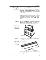
Page 43: ...ectly from ELTRON Supplies can be or dered from ELTRON by calling 1 800 344 4003 Step Open the printhead assembly and remove any labels loaded in the printer see Figure 2 2 Hand rewind the labels back onto the roll Step Gently rub the Cleaning Pen across the amber area of the printhead Allow the print head to dry for 1 minute before reloading the labels Printhead Figure 2 19 Locating the Printhead...

Page 44: ...w the steps below to replace the battery Battery Replacement Step 1 Turn the printer on with the Memory Cartridge installed for minimum of 5 minutes This is to prevent data loss while replacing the battery Memory loss will occur if this process is not completed in approximately 5 minutes The discharge of electrostatic energy that accu mulates on the surface of the human body or other surfaces can ...

Page 45: ... top cover off See Figures 2 21 and 2 22 Step 4 Lift the battery retaining clip up and slide the battery out Cover Screw Figure 2 21 Removing the Memory Cartridge Cover TOP COVER SRAMS BATTERY TIME DATE CHIP TOP COVER SCREW EPROM BATTERY RETAINING CLIP Figure 2 22 Memory Cartridge Components Operation 980003 003 Rev A 39 ...

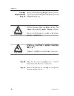
Page 46: ...he battery may explode causing damage or injury Dispose of the battery according to the manu facturer s instructions INSTALL BATTERY WITH PRINTED SIDE UP Improper installation can damage the printer Step 5 Slide the top cover casing back on Lock the cover shut with the top cover screw Step 6 Re insert the Memory Cartridge into the printer and turn the power on Operation 40 980003 003 Rev A ...

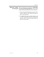
Page 47: ...tting guidelines should be followed The top margin should always be set to 0 16 4mm to allow for the unprintable region at the top of each label The right left margin should always be set to 0 04 1mm less than the actual label width to allow for the unprintable region at the side of each label Operation 980003 003 Rev A 41 ...

Page 48: ...Operation 42 980003 003 Rev A ...

Page 49: ...t Web Address http www eltron com eltron e mail techsup eltron com BBS 805 579 3445 The BBS supports data rates up to 28 8 BPS with No Parity 8 data bits and 1 stop bit n 8 1 Communications software should have an ANSI Terminal Mode not MS Win dows Terminal such as Q Modem CompuServe e mail 102251 1164 Customer Service 800 344 4003 To order printer supplies and accessories Eltron accepts Mastercar...

Page 50: ...that the Printer Control Switch position 8 is correct Printing stops and the ERROR indicator lights AMBER ORANGE 1 Possible problem with label gap sensor Perform AutoSense adjustment 2 Possible problem with label stock Gap between the bottom of a label and the top of the next label should be at least 1 16 For tags see Figure A 2 Use only Eltron approved labels and tags 3 Possible label jam 4 Check...

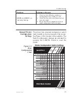
Page 51: ...he switches The Switch configuration changes are activated by pressing the CANCEL button to reset the printer 1 2 3 4 5 6 7 8 Printer Configuration Switch Settings Ba u dRa t e St o p B i t Da t aL e n g t h Da t aL e n g t h P a r i t y Function Switch Positions 1200 Bits Sec 2400 Bits Sec 9600 Bits Sec 19200 19 2k Bits Sec Even Parity On Odd Parity On Parity Off 2 Stop Bits 1 Stop Bit 7 Bit Data...

Page 52: ...2 3 3 4 4 5 5 6 6 7 7 8 8 9 9 DB 9 Pin DB 9 Pin Female DB 9 to Male DB 9 N C RxD TxD DTR GND DSR RTS RI CTS Printer Host 1 8 2 3 3 2 4 20 5 7 6 6 7 4 8 5 9 22 DB 25 Pin DB 9 Pin Female DB 25 to Male DB 9 5 volts at 150 mA for external device e g KDU or scanner 5 Volts TxD RxD N C GND RDY N C N C RDY 5 Volts TxD RxD N C GND RDY N C N C RDY Trouble Shooting 46 980003 003 Rev A ...

Page 53: ...located under the label guide and sliding the sensor in or out For proper sensing ensure that the sensor is aligned with the center portion of the index hole notch The following dimensions show the required position of the Sense Through Notch hole on tag stock for the TLP2046 printer Dimension Min Max Nominal A 236 None 512 B 079 512 118 C 098 216 N A B C A 314 Nominal Sensor Location min max Insi...

Page 54: ...tions The TLP 2046 and TLP2044 are part of Eltron s heavy duty line of industrial printers The TLP2046 has a 4 inch print width 203 dpi print resolution and up to 512KB user config urable memory It prints in both direct thermal and thermal transfer mode The TLP2046 prints up to 6 inches per second with the TLP2044 at up to 4 inches per second User Features Performs self test and prints out it s co...

Page 55: ...ee print modes are included as standard Batch printing one or more labels with the labels left on the backing paper Rewind printing a batch of labels and re winding them inside the printer Peel off labels dispensed with label backing material removed and rewound inside the printer A Label Present Sensor stops the printer from printing and dispensing the next label until the first one is removed Ba...

Page 56: ...ension 005 12mm to 050 1 27mm Standard Fonts Five alpha numeric fonts from 049 degrees 1 25mm to 23 degrees 6 0mm high All fonts are expandable vertically and hori zontally up to 8x Fonts can be printed in four directions 0 90 180 and 270 degrees International character sets standard Any font or PCX graphic field can be down loaded from CREATE A LABEL Media Sensing See through sensor for die cut l...

Page 57: ...Minimum media length 0 5 12 7mm Thickness including liner 0 0025 to 0 0100 0635mm to 254mm Supply roll capacity 8 203mm maximum O D outer diameter and 3 76 2mm minimum I D inner diameter Capacity of internal rewind 0 5 12 7mm Fanfold stock can be fed through a slot in the rear panel of printer Ribbons Standard widths 1 3 933mm 2 5 64mm 3 3 84mm 4 3 109mm Length 14 270 362mm and lengths for a 1 2 r...

Page 58: ... F 5 degrees C to 40 degrees C Storage Temperature 4 degrees F to 158 degrees F 40 degrees C to 70 degrees C Humidity 10 to 95 non condensing Ventilation free air Options RS 422 Interface Memory expansion modules up to 512K Time and Date Clock Media Length up to 22 560mm Code PDF417 Create A Label III software Create A Label Professional for Windows Windows Printer Driver Used with Eltron s KDU fo...

Page 59: ...Number Parallel Interface Cable 6 Parallel Interface Cable 10 Serial Interface Cable 6 DB 9 to DB 9 Serial Interface Cable 10 DB 9 to DB 9 Serial Interface Cable 6 DB 25 to DB 9 300016 006 300016 010 300017 006 300017 010 300018 006 Memory Cartridge includes 2D barcodes 384K Cartridge without Real time Clock 384K Cartridge with Real time Clock 105200 009 105200 010 Automatic Label Tag Cutter Label...

Page 60: ...ansfer combination Most commonly used Low environmental durability Low abrasion resistance Longer life than direct thermal Ribbon Not Used Wax Media Stock Paper Label Tag Synthetic Label Paper Label Tag Typical Applications l l l l l l Shipping Inventory Tracking Shipping Inventory Tracking Product Labeling Compliance Labeling Direct Thermal Thermal Transfer Accessories 54 980003 003 Rev A ...

Page 61: ... expensive label tag combination Ribbon General Purpose Resin Hard Resin Media Stock Paper Label Tag Synthetic Label Synthetic Label Typical Applications l l l l l l l l Retail applications where labels are handled Excellent for most applications Compliance Labeling High temperature environments Medical applications Outdoor environments Environments with chemicals Compliance labeling Thermal Trans...

Page 62: ...Accessories 56 980003 003 Rev A ...

Page 63: ...utton the printer list is dis played Under the List of Printers select Install Unlisted or Updated Printer When prompted for the location of the driver enter the drive where the diskette is i e A or B Click OK Select the TLP2046 driver that represents your printer The printer driver is installed and ap pears in the Installed Printers list in the Printers dialog box Windows For Workgroup Users If y...

Page 64: ... accessed through the Print ers control panel in the Program Manager Main group Paper Label Size Before creating a label the paper size for the currently loaded labels must be selected in the control panel Setting the proper label size allows the driver to provide accurate printing limits and margin information to other Windows applications in cluding Create A Label Professional Windows Printer Dr...

Page 65: ...u select Options from the printer setup control panel Print Quality Print Density The print darkness or density can be changed by using the Print Quality option If print looks faded when printing at high speed select a higher darkness number for the Print Quality setting If horizontal lines seem to run together select a lower darkness number Print density is also affected by print speed Changing b...

Page 66: ...Windows Printer Driver 60 980003 003 Rev A ...

Page 67: ...Windows Printer Driver 980003 003 Rev A 61 ...

Page 68: ...41 Moreland Road Simi Valley CA 93065 805 579 1800 FAX 805 579 1808 ...

Reviews: